Sovelia Plant offers the ability to create cable trays, adding another level of detail and functionality to your plant models.
General information
Connection
Cable trays uses a new connection type called ”Cable Tray”.
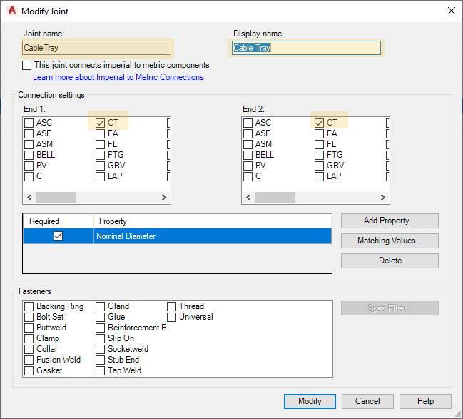
This connection type must be added to existing projects. This is done in the Project setup. Alternatively, the setting can be copied from DefaultconnetcorsConfig.xml in the Sovelia template project. Do not hesitate to ask Symetri for help with this if any issues arise.
Specs
Routing a cable tray is as easy as routing a pipe. When using a Sovelia Plant template project, simply choose Cable Tray Ladder, Cable Tray Ladder Reinforced (for 2025.1 and later) or Cable Tray Mesh under the list of available pipe specs and route as you would a normal pipe.
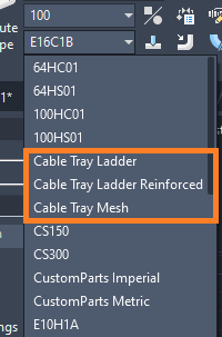
The Cable tray ladder contain sizes between 100-1000, and the reinforced one has the sizes 400 and 600. The cable Tray Mesh works for sized 50-600. It is important to note that the trays are generic models, and do not adhere to any manufacturer standard. Dimensions and descriptions of the components can be edited in the properties palette.
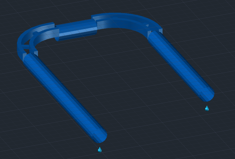
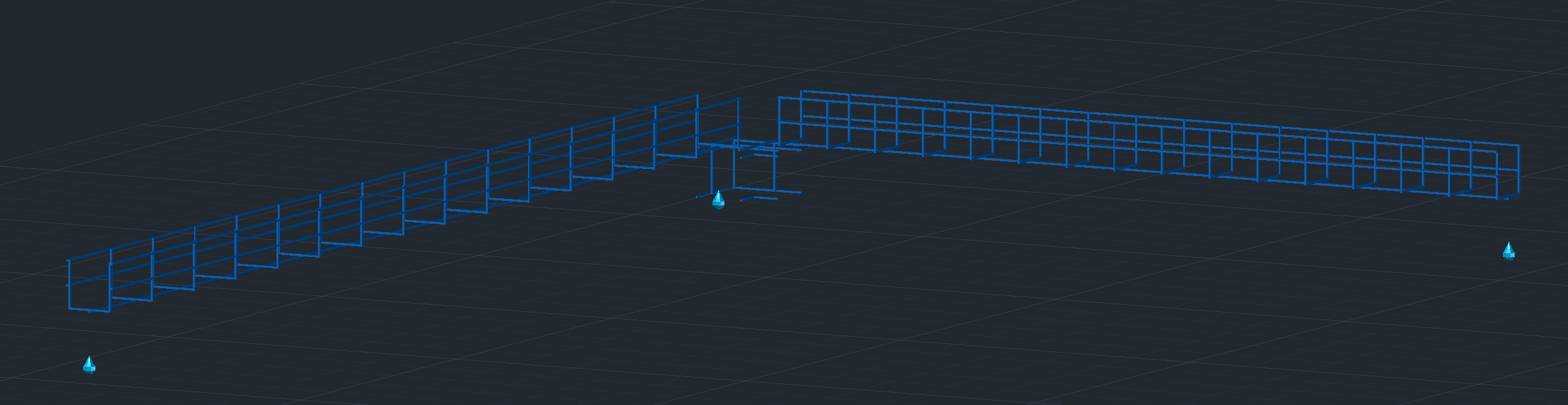
Straight sections of the cable trays look like pipes initially due to limitations in Plant 3D. However, Sovelia Plant offers four commands for editing and finalizing the model.
Functions
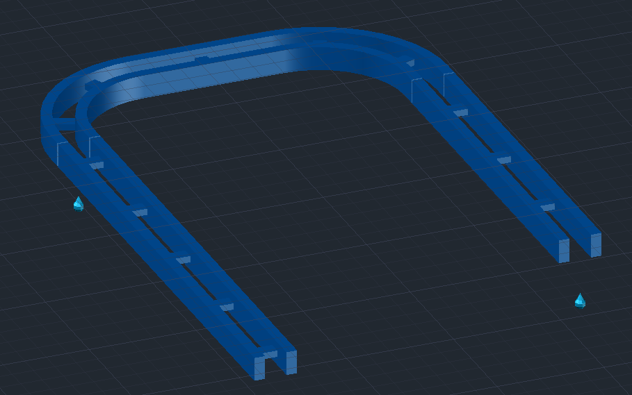
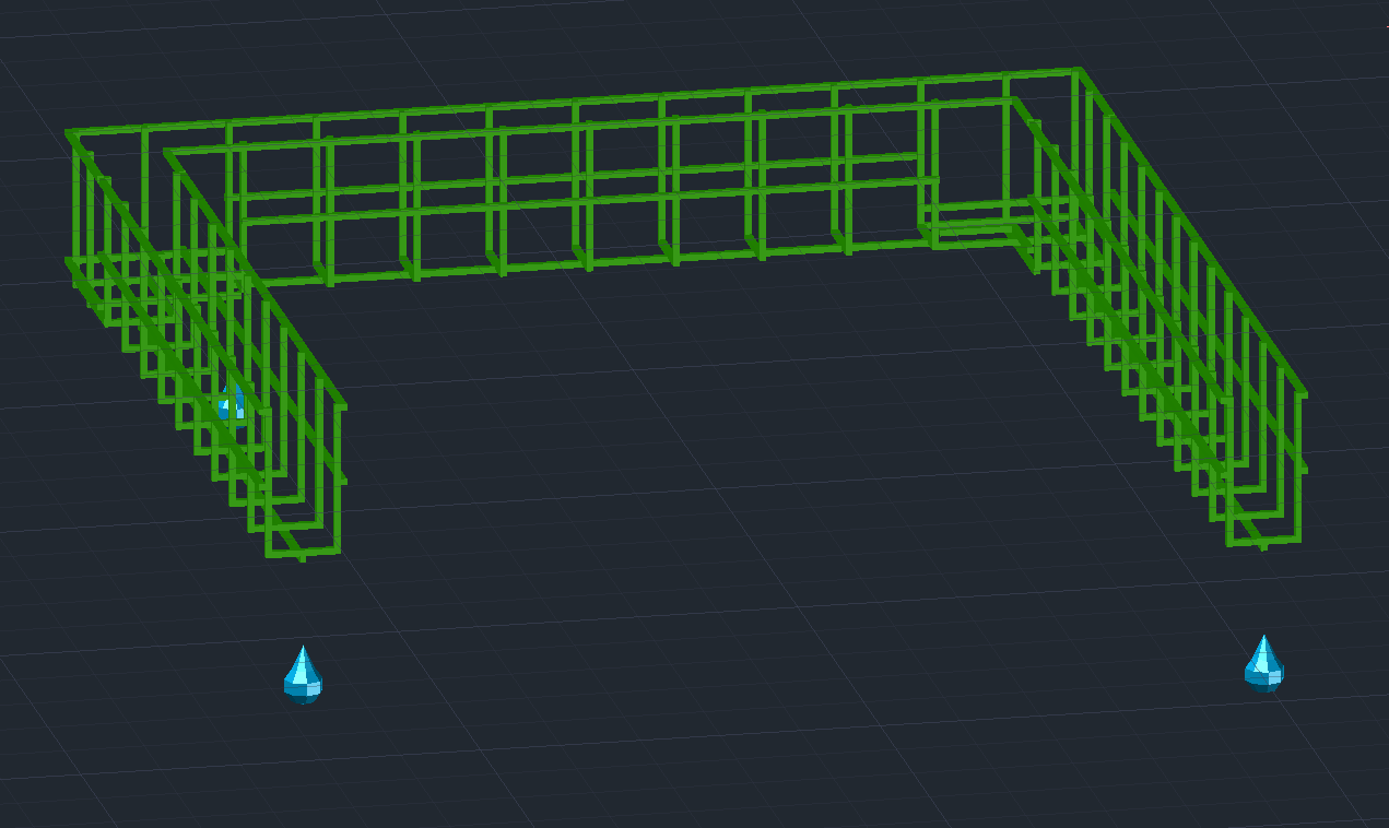
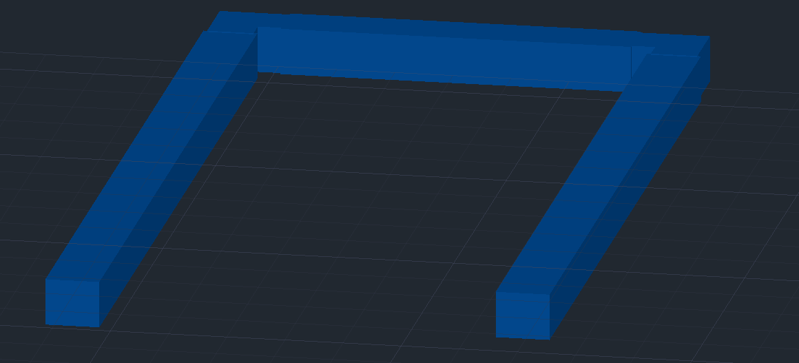
Convert to tray

This command converts the graphical look of the cable tray from the pipe representation to the final detailed model.
Ladder:
Mesh:
Flip tray

The command flip tray is a simple function used to flip pieces of cable trays that are upside down. When routing the cable trays, some components are likely to be routed upside down due to limitations in Plant 3D. However, the Flip Tray command solves this problem easily. Simply select the command, and click on the segment of the tray:
The tray is now flipped to align with the other segments.
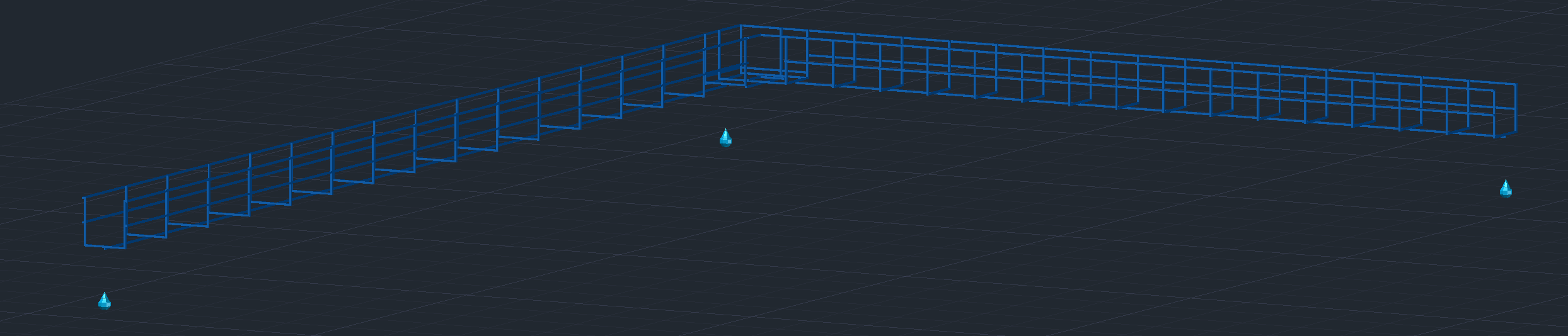
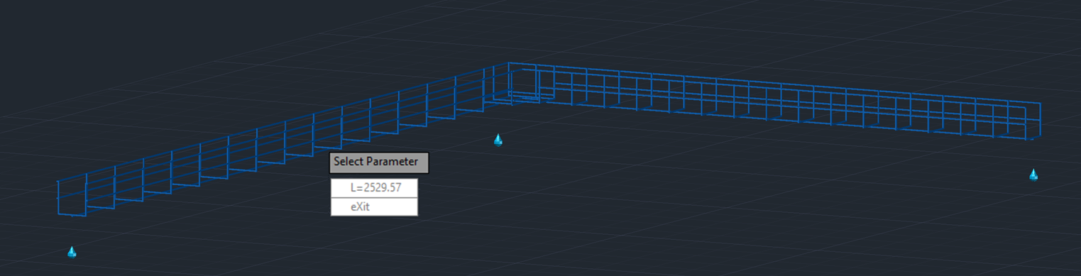
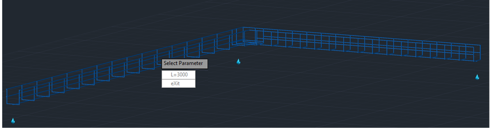
Stretch tray

The Stretch tray command is used to edit the lengths of the cable tray segments after they have been placed. By using the command and selecting a segment, the user can easily adjust this parameter.
Cable tray sizes can be edited in the properties palette.
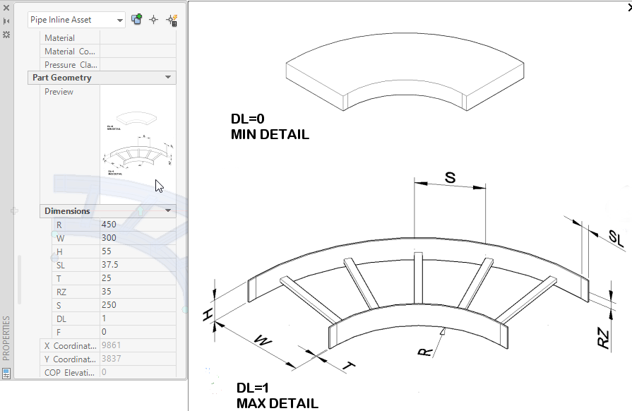
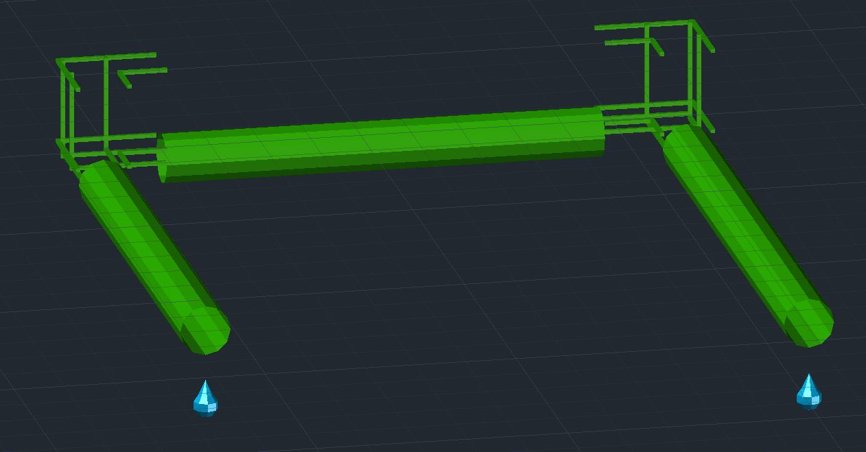
Flip detail level

The Flip Detail Level function is used to lower the graphical complexity of the cable trays to conserve performance while working on large or intricate projects. Simply select the command and click on the segments you want to lower the complexity of.
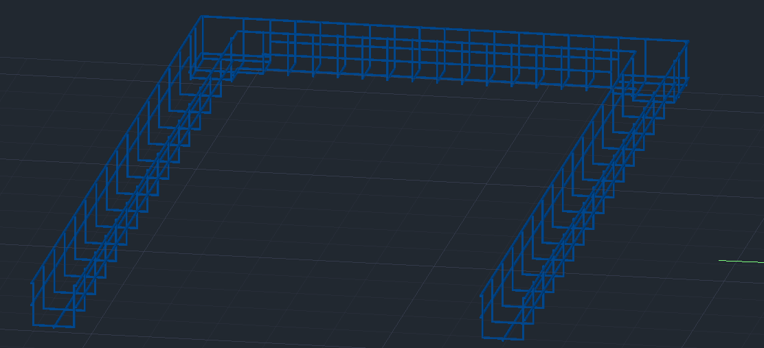
The cable trays now resemble pipes with a rectangular profile, and the system will have an easier time rendering the drawing.
Substitute components
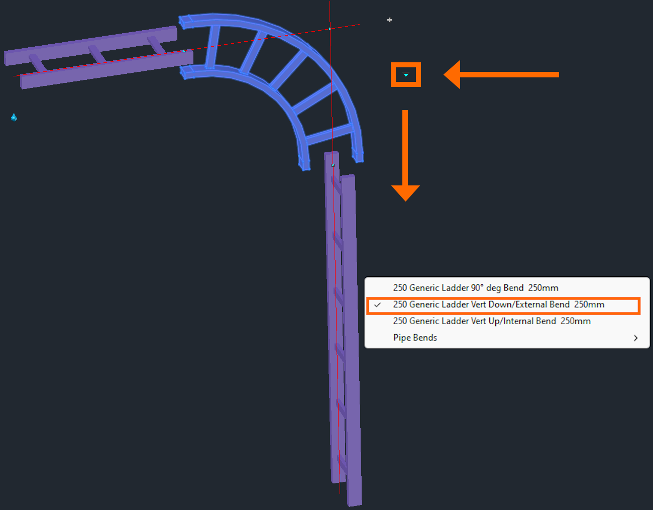
When routing trays vertically the Plant 3D substitute command is necessary.
There are two different types of bends:
Vertical Down / External Bend
Vertical Up / Internal Bend
Depending on which you choose the bend will be either connected correctly or incorrectly.