Drawing Templates
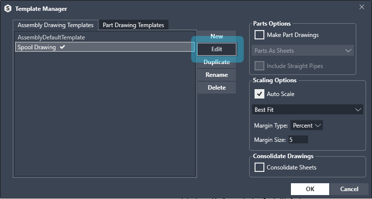
Assembly drawing templates
Select a template in the list and click Edit to configure assembly drawing template according to your needs.
Views placement (Inventor native command)
Start the drawing configuration by choosing which views you want in the drawing by using the Inventor native place view commands, Base.
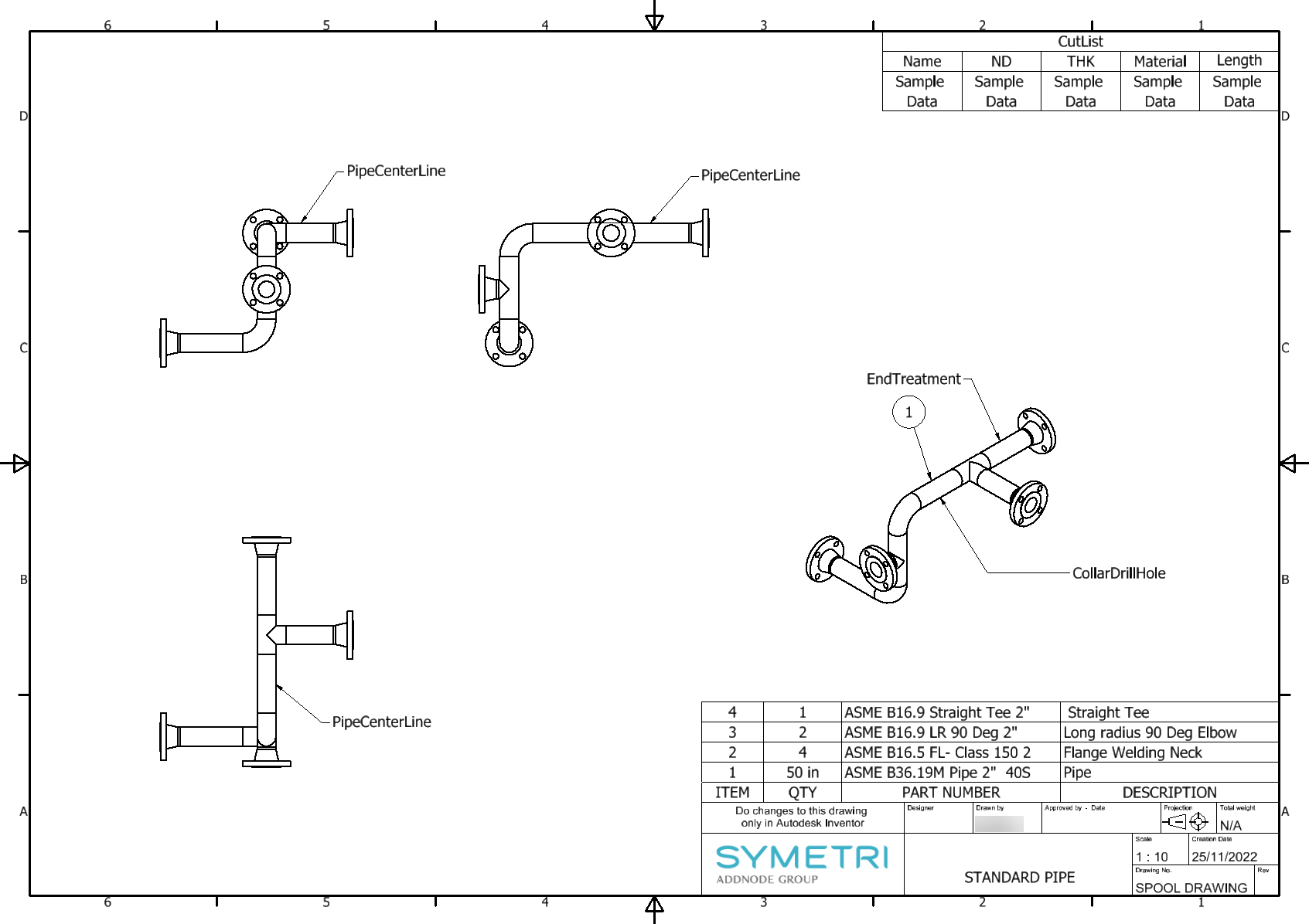
Parts List placement (Inventor native command)
For Parts List use Inventor native command, Parts List. Place your parts list
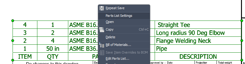
Right click on the parts list and choose Parts list settings in the contex menu. Set postion and BOM view settings for the Parts List.
In the Parts List settings you can choose Position and BOM View (Strctured or Parts Only)
Other drawing features
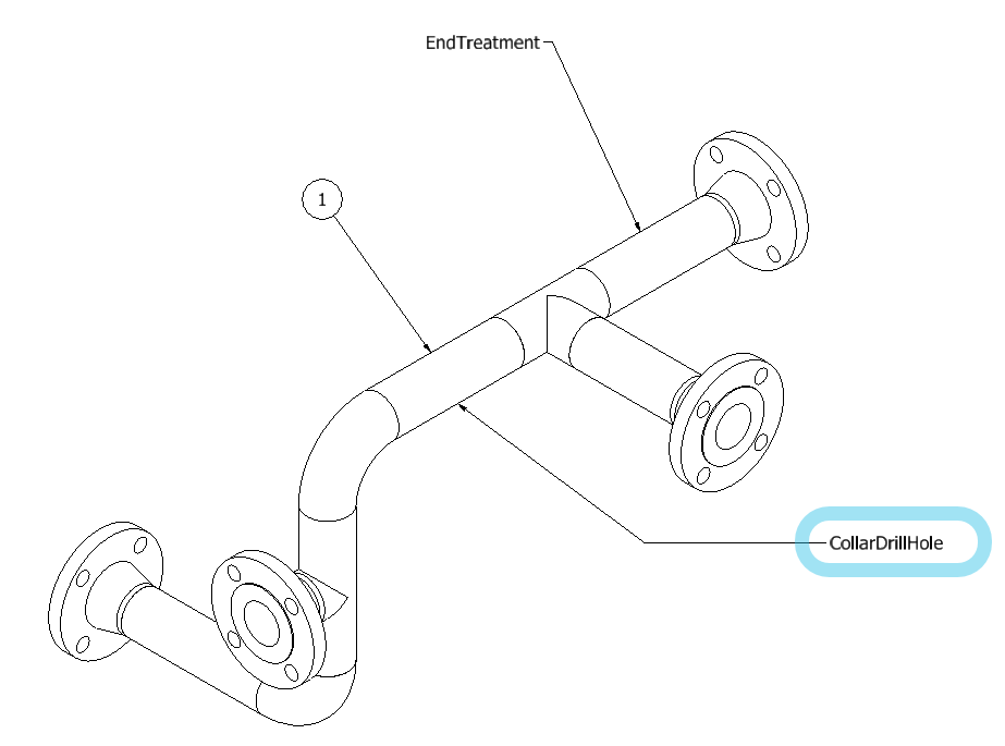
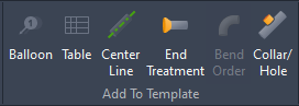
For Balloon, Cut List table, Center Line, End Treatment annotation, Bend Order table and Collar/Hole annotations you will use [S] Routing commands from the Add To Template panel.
Balloons placing
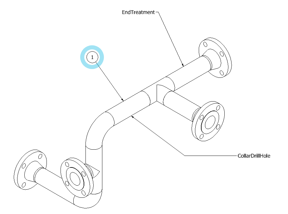
To add Balloons, use [S] Routing, Balloon command and attach a leaded text to a curve in the view where you want the Balloons to be placed.
Cut List table creation
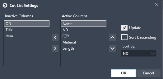
To add a Cut List table, use the [S] Routing, Table command and configure which columns to display in the Cut List table.
Center Line creation
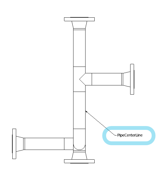
To add Center Line, use the [S] Routing, Center Line command and attach a leaded text to a curve in the view where you want the annotation for Center Line to be created.
For pipe assemblies you also need to activate the Center Line option in the settings menu, general tab.
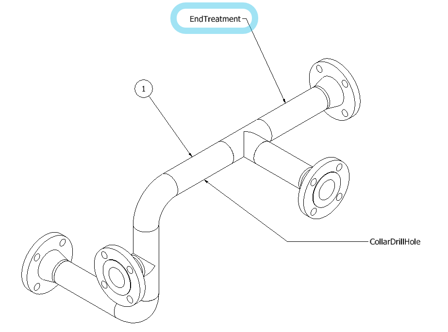
End Treatment / Forming annotation
To add End Treatment / Forming annotation, use the [S] Routing, End Treatment command and attach a leaded text to a curve in the view where you want the annotation for End Treatment / Forming annotation to be placed.
Bend Order / XYZ Table is not applicable in the assembly drawing
Read more in the Part Drawing Settings
Collar / Hole annotation
To add Collar / Hole annotationn, use the [S] Routing, Collar / Hole command and attach a leaded text to a curve in the view where you want the annotation for Collar / Hole annotation to be placed.