
Background
There are many standard methods to export a DXF file of sheet metal parts from Inventor, either from the sheet metal flat pattern, the drawing of the flat pattern, or even by right clicking on a face in a sheet metal part. However, there is no standard batch routine to export an entire design (assembly) to separate DXF files, and certainly no method to allow configured file naming, export location, and included text inside the generated DXF files. This tool has therefore been created to automate these processes.
Accessing the Tool
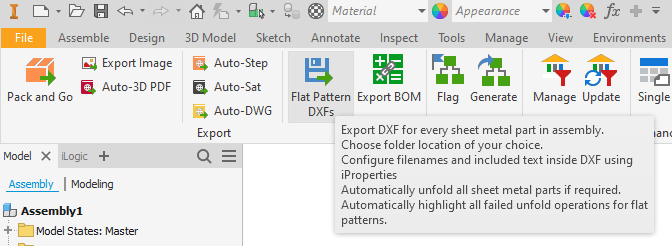
The tool can be accessed in the toolkit ribbon as shown below.
Using the Tool
The tool is designed to be simple to use. Follow the steps below:
Export Location
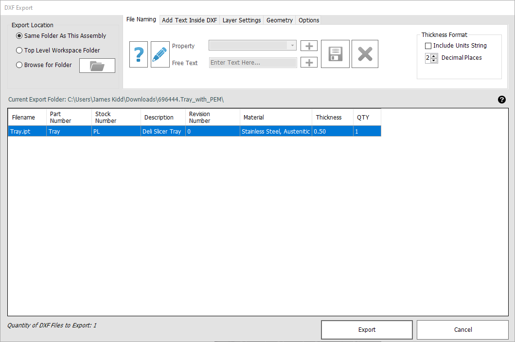
- Pick the export location for the DXF files. Note this will be remembered for next time. The top option (Same Folder as This Assembly) will always save the DXF files relative to the current assembly file, the ‘Top Level Workspace’ option is dependent on the active Inventor project file, and the ‘Browse for Folder’ option allows you to specify a fixed folder for all future exports.
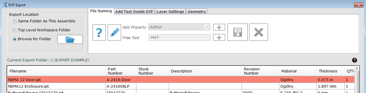
File Naming
- Choose your file naming convention. Use the ‘pencil’ button to create a new file naming format based on iProperties or free text that is fixed for all DXFs. Note that the format displays visually in the lower window as you are building it. Hit the ‘Save’ button when you are finished. Note there is no option to ‘undo’ this process, so if you hit the wrong button, it is best to cancel and start again.
Once you have saved the format, you can use the ‘Question Mark’ button to check whether it is correct or not. If you have made a mistake, then use the pencil button to try again.
Add Text Inside DXF
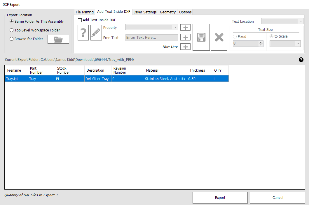
The tool can insert text inside the generated DXF files as part of the export operation. As with the file naming, you can specify what iProperty values should be written inside the DXF files, and also QTY information for each part.
You can enter ‘multi-line’ text into the DXF files, simply by using the ‘New Line’ button between properties.
You can enter fixed text to be included inside the DXF files also if desired.
You can specify the location of the DXF text in the exported files. Note that this will ‘stick’ to the outside extents of the DXF file to allow for the text to be easily identified by a human operator.
You can specify a fixed text height, or alternatively a variable text height based on the size of the flat pattern. This can be useful for human readers, as when the DXF is ‘fit-to-screen’ in AutoCAD (or another program) the text will always be shown at a visible size, whether the DXF file is 1000mm across, or 10mm across. Note the ‘To Scale’ fraction is the diagonal size of the DXF.
Layer Settings
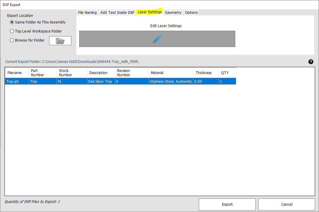
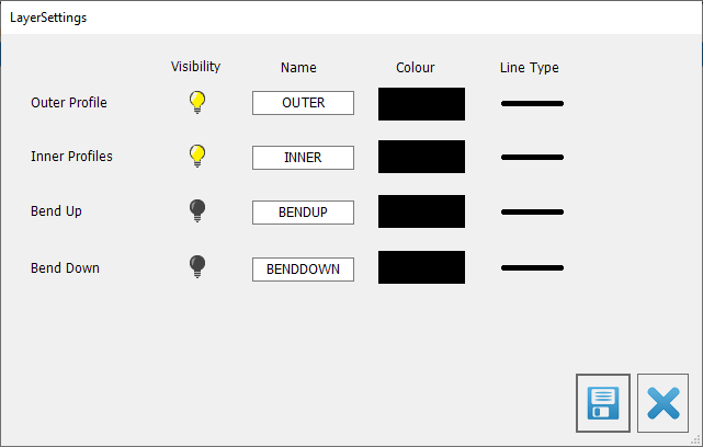
Hit the pencil button to choose the layer settings for the export.
In the example dialogue below – the user has specified that the ‘Bend Up’ layer should be invisible, the Outer and Inner profiles should be solid lines, and the ‘Bend Down’ layer should be dotted.
Geometry
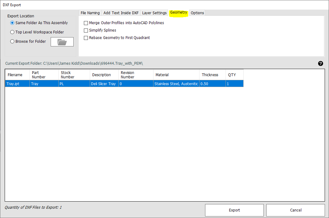
Use the ‘Merge Outer Profiles to Polylines’ in order to create a single polyline from all the external edges of the sheet metal part.
Use the ‘Simplify Splines’ option to convert complex splines to multiple straight-line sections – this may be required for certain machines.
Use the ‘Rebase Geometry’ option to move the DXF geometry to be placed on 0,0 XY coordinates. Note that this method may occasionally not move the geometry into precisely the correct location, however this is a limitation with the Inventor functionality exposed in the programming interface (API)
Note: the above options are exactly comparable with the standard options that are available when manually exporting DXF files from Inventor.
Options
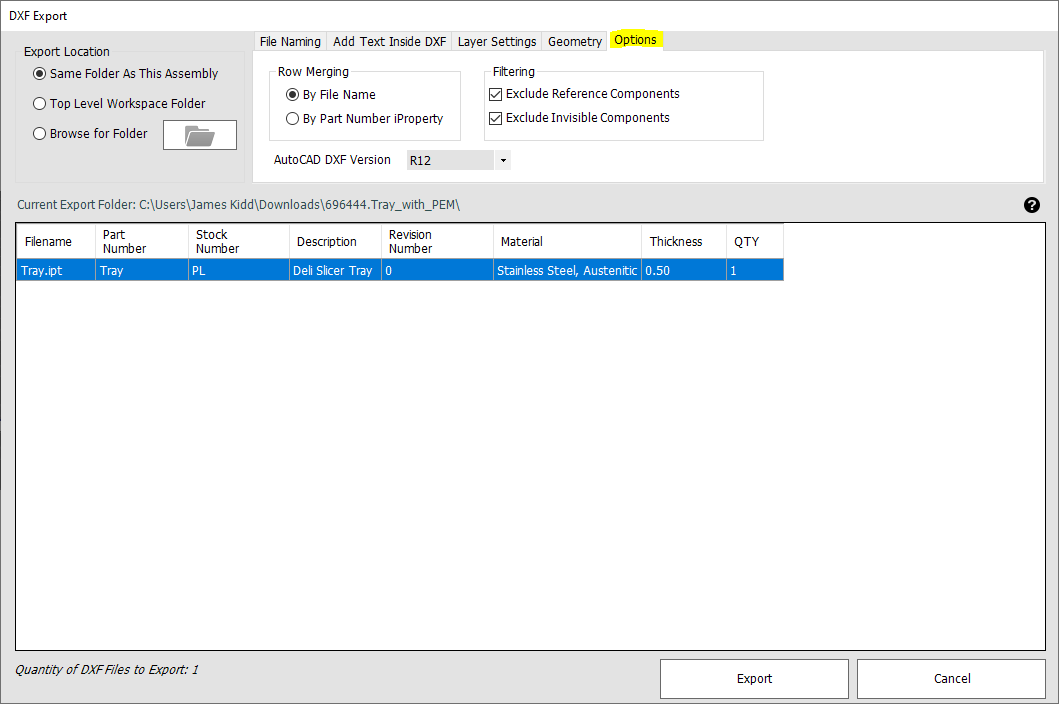
These options allow you to choose whether to merge different file quantities into a single DXF, and whether to include or exclude reference and invisible components.
Row Merging
By default, Inventor will make the ‘Part Number’ iProperty of all new files identical to the filename on the system (without the file extension). In this case, these merge options will have no effect, as the Part Number and Filename are the same. The quantity of each sheet metal component will be the total instance quantity of that file in the entire assembly.
However, you may have rules or concatenation defining Part Numbers that are different to the filenames of your sheet metal components. In this case it can be useful to merge the quantities of components with identical filenames, by ticking the ‘By Part Number iProperty’ box.
Filtering
If the ‘Exclude Reference Components’ box is ticked, then any sheet metal components that have their BOM structure set to Reference in the assembly Bill of Materials (BOM) will be excluded from the export (and will not be shown in the preview table).
If the ‘Exclude Invisible Components’ box is ticked, then any sheet metal components that are currently not visible (have their visibility un-ticked) in the assembly will be excluded from the export (and will not be shown in the preview table).
Note that applying either of these filters requires Inventor to search through each individual component instance in the assembly. More processing is required, so the export dialog will take longer to appear. Export times are unaffected.
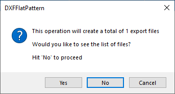
Export Button
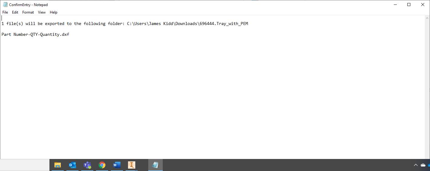
When the export button is hit, there is the option to see the list of filenames that will be created, before the export begins. The user can also view which files will be overwritten by the operation (if any). If the list is not as expected, or the file naming appears different from expected, hit the ‘No’ button to re-configure the setup.
The export will then continue. Typicaly each sheet metal component will take between 0.2 and 1 seconds to export, depending on your hardware spec, the complexity of the sheet metal component, and whether the sheet metal component already contains a flat pattern representation (has been unfolded and saved previously).
If any parts are found to not already contain an unfolded flat pattern, the program will attempt to unfold them as part of the operation. This can fail in Inventor for many reasons, such as below:
- Geometry is not a constant thickness.
- Geometry self intersects when unfolded.
- Incorrect sheet metal rule is applied.
If any components fail to export, the user is provided with methods to evaluate this. See next section.
Investigating Export Failures
When the export is complete, the user is informed of any failed exports.
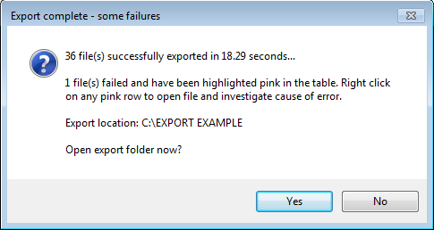
The user can open the export folder at this point if desired.
If desired, the user can view a log file showing information for which files have succeeded, and which have failed.
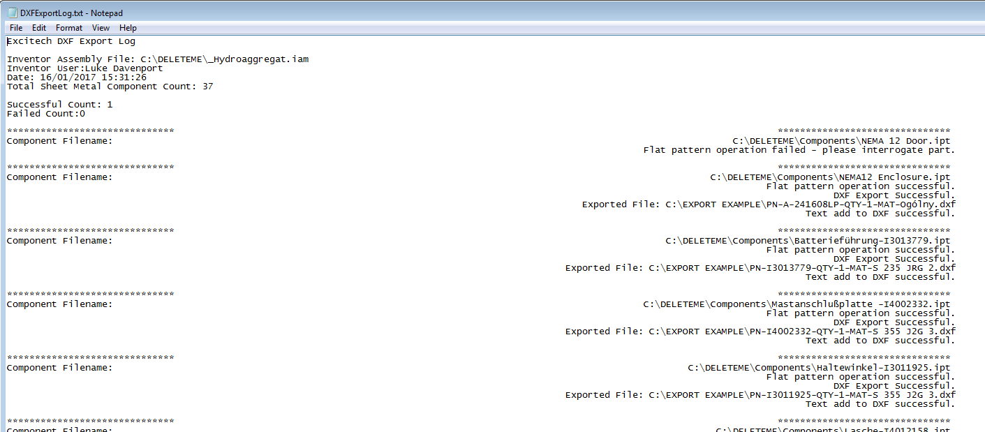
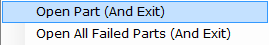
Any files that have failed will also be highlighted pink in the table. These can be right clicked and opened directly from the table, to allow the reasons for failure to be investigated.
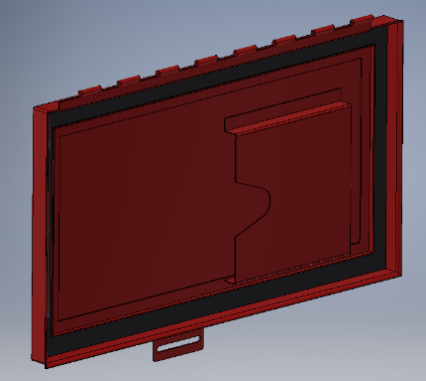
It will normally be very clear why a part has failed to flat pattern and export. For instance the below part has been modelled as a single sheet metal part, which obviously cannot be unfolded into a single flat pattern.
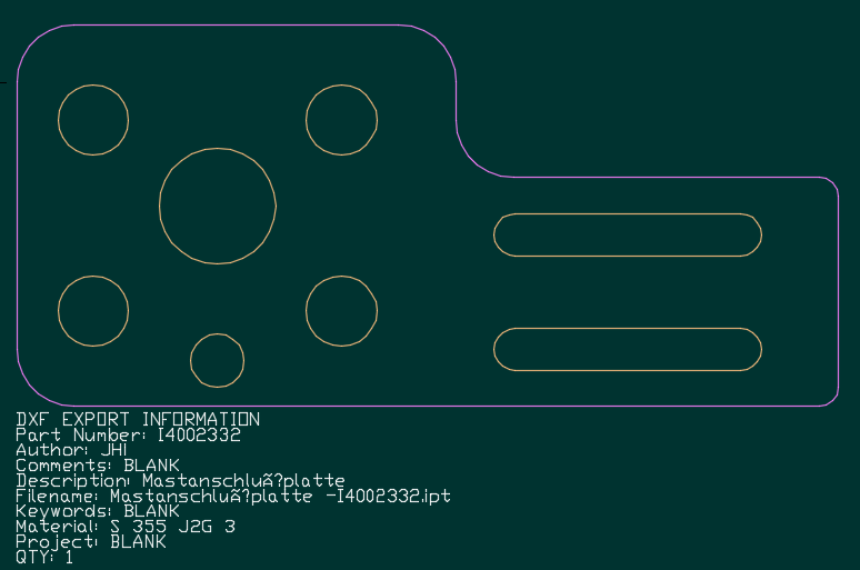
Below is an example of an exported DXF file with included DXF text specified in the bottom left corner.
Notes (FAQ)
Q: How are the quantities of each sheet metal part obtained?
A: The quantity of each sheet metal component in the assembly is the total instance qty of that file in the entire assembly, including all sub-assemblies. If a sheet metal component is contained within several sub-assemblies, the QTY shown in the export will be the total sum of all the occurrences. See the ‘Options’ section above for the merging and filtering options.
Q: How about component suppression?
A: If you have any components suppressed at any level in the assembly, they will not be recognised as part of the export. If you have 4 instances of part ‘12345.ipt’ active, and 2 instances suppressed, the displayed quantity will be 4.
Q: How about component visibility?
A: See the Options section above.
Q: How about reference components?
A: See the Options section above.