Iso Processing
When generating isometric drawings, the drawing commonly gets split into several sheets. The number of sheets can be unpredictable and may vary even after minor changes. The Iso Merge function was developed to address these issues, and is used to merge all sheets into one file.
Running Iso Merger
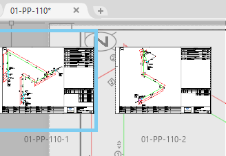
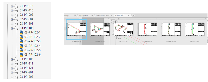
The Iso Merge function consolidates all sheets of a chosen line into a single drawing, placing each sheet on a separate layout tab. This not only simplifies file management, but also makes viewing the isometric easier.
To run the function on a single line, do the following:
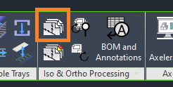
Open any sheet from the first line and press the Iso Merge button.
A new drawing opens, and all sheets are added to separate layouts.
The new drawing is saved to a specified location.
Repeat for each line.
There is also the option of running Batch Iso Merge for multiple lines:
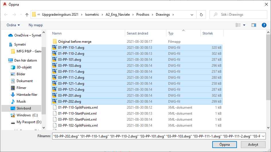
Press the Batch Merge Iso button.
Select the generated isometrics.
Press “Open”.
The program consolidates the sheets for all lines into one drawing for each line.
The system saves the drawings to a specified location.
Template drawing for Iso Merge
A few things are important to remember when setting up a Template Drawing:
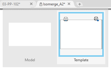
A layout with the same name as specified in Layout Settings must be present on the drawing “Isomerge_A2.dwg”. The default name is Template.
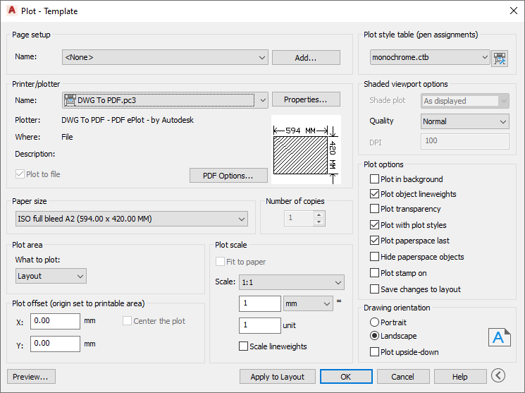
A current page must be selected in the Layout. The default page setup in the A2 template is A2.
To prevent accidental overwrites, write protection should be enabled on the template file.
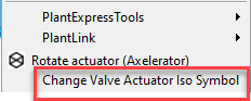
Valve Actuator Iso Symbol
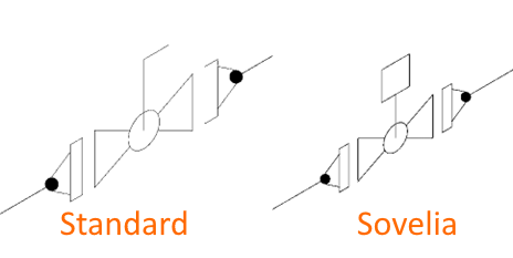
Isometric symbols only come with a basic hand lever in standard Plant 3D. This default symbol is inaccurate when an actuator is mounted on a valve.
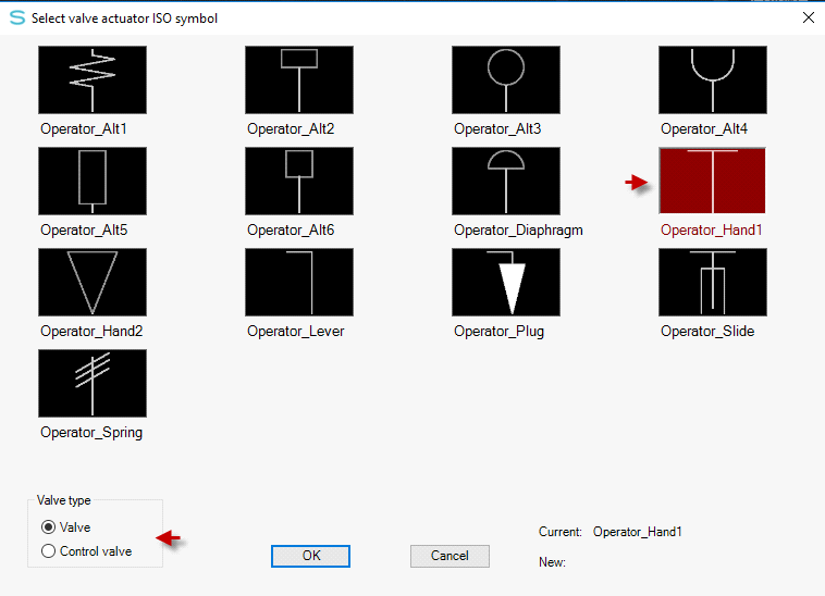
Sovelia Plant has a solution for this problem. By right clicking on the valve and selecting “Change Valve Actuator Iso Symbol” the symbol can be changed. With this method isometrics can be generated with the correct symbol.
Custom valves created as instruments can be switched to valves (and vice versa) if needed
Ortho Processing
Updating orthographical drawings can take anywhere from a few minutes to several hours. While waiting Plant 3D is locked, and no further work can be done. After completing the update the process has to be repeated for the next drawing. Thankfully Sovelia Plant has developed the Ortho Update function which runs all views one after another until they are all updated.
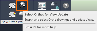
To prepare the Ortho Drawings, start by activating “Select Ortho Views for Update” in the Ribbon.
The first time running the command the system will prompt you to create the necessary .XML file.
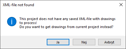
Once this is done a dialogue opens where settings can be adjusted.
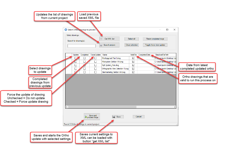
Drawings that have been updated earlier will be checked as completed.
The user selects which drawings to update by checking Update. This selection can be saved with the “Save” icon. This way the selection can be done in advance of the actual update. By clicking “Save and Process dwgs” the “Update Views on Selected Orthos” command is run. It is important to make sure that no selected ortho drawing is open when the processing starts.
BOM and Annotations
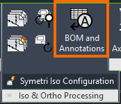
The BOM and Annotations command opens a palette which can be used to annotate Ortho drawings in a simple and fast way. The secondary BOM tab holds a similarly extensive collection of tools for editing BOMs.
Annotation Toolbar
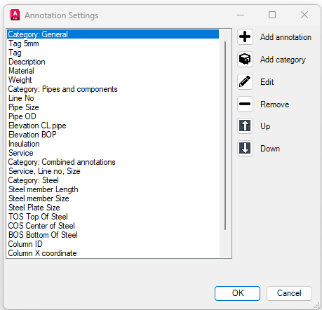
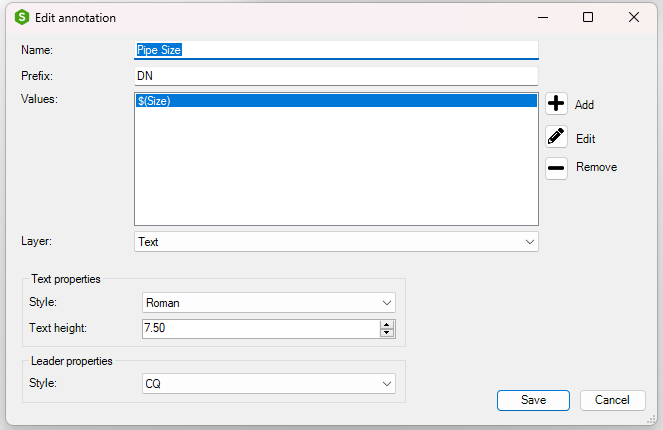
The Annotation Toolbar function allows for easier and more efficient ways of annotating ortho drawings. Activating the command opens a toolbar with a selection of annotations, either with or without a leader. Additionally, original annotations can be created in the configurator window. Existing annotations can also be edited.
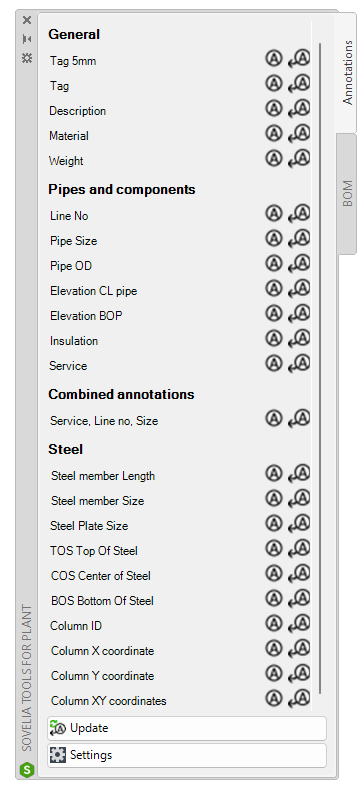
If database fields are changed, the Update annotations button the annotations are refreshed to contain the new values.
BOM editing
Furthermore, the BOM tab contains functionality for creating and editing BOM lists.
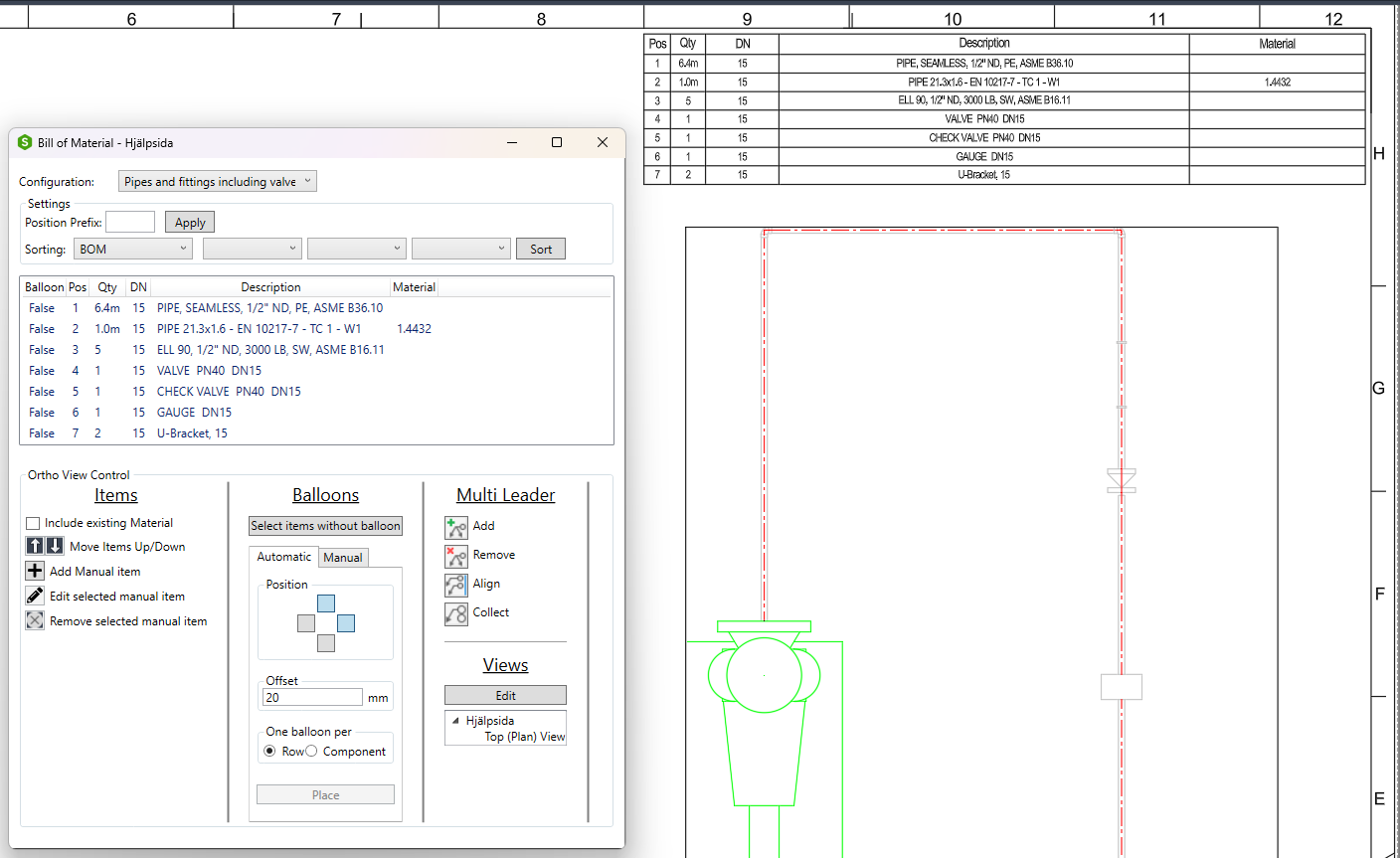
To initiate the function, click on the "Ortho Annotations" button. This action will open the customization tab. Within this tab, standard BOM tables are available if the "BOM" tab is selected. Customization options for BOMs can be found at the bottom of the interface.
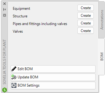
The "Edit BOM" function allows modification of an existing BOM placed on a drawing. The "Update BOM" function refreshes the BOM by synchronizing it with the database to reflect any textual changes to associated objects. The "Configurator" button opens a separate window, enabling customization of the BOM query and table structure, including column count and order.
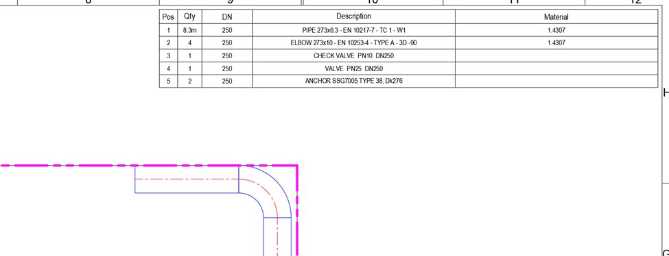
After selecting the desired BOM configuration the BOM table and choosing the related viewport and pressing “enter” on the keyboard the BOM is automatically placed at the predefined insertion point for BOMs in Ortho drawings, which is typically located in the top right corner.
The edit window provides various options for adjusting the table and positioning POS balloons. The top section allows users to select an alternative BOM table if the initial selection was incorrect. Note that changing the BOM table will result in the removal of any previously placed annotations.
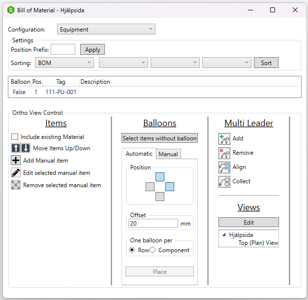
The "Prefix" dialog enables users to define a specific letter or number prefix, such as "A1," for the BOM table. After entering the desired prefix, click "Apply" to update all POS numbers accordingly.
Sorting options are available for organizing the BOM table. The default sorting method arranges numbers sequentially from the top of the table, starting at "1." Alternatively, selecting the "By Location" option arranges the numbers based on their placement within the drawing view.
Further sorting customization allows users to define the primary sorting criterion. For instance, the table can be sorted first by "Description" and then by "Material." Click the "Sort" button to apply these changes.
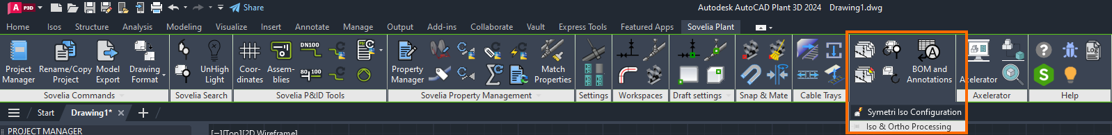
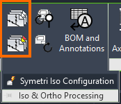
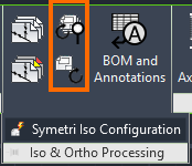
Symetri Iso Configuration
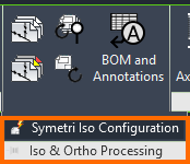
The iso configuration options are accessible by expanding the Iso and Ortho Processing menu. Clicking the button opens a menu with many configuration options for efficient Iso generation.
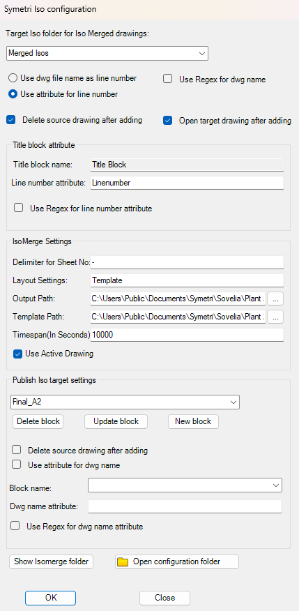
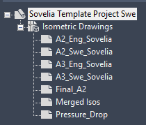
In the first part of the menu the target folder for the Iso exports can be chosen. By default, the merged isometric drawings are stored in the merged Isos folder.
The next section of the options menu concern the naming of the generated Iso files. A user can chose to use the dwg file name, or perhaps an attribute, as the file name. There is also the option of using Regex to configure a name based on multiple inputs.
The last options in the section are whether the source drawing should be deleted from the Isometric drawing map structure in the project manager. There is also the option of opening the drawing after the merging process is finished.
In the next section the title block name is set. If the attribute option was chosen previously, here is where the chosen attribute is chosen, by typing the name.
Next are the IsoMerge settings, where such things as delimiters, layout settings (fixed string, do not change this value), and output paths are set. The template path determines which Iso template is used in the merging, and should correspond to the one used for the initial Iso generation.
The timespan settings determines the maximum time the system should allow between the generation of the pages of an isometric drawing. Meaning if a page is edited 10000 seconds after the Isos initial generation, it would no longer include the other pages in the merging. The option ensures only pages with a similar creation date are included in the merging.
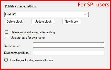
The last section is strictly for users of the Sovelia technology SPI, Symetri Plant Integration. SPI is a plugin that connects the functionality of Plant 3D, with the ALM (Asset Lifecycle Management) SiteBase. As such, settings should not be changed from the default by any non-SPI user.
The last buttons, Show Isomerge folder and Open configuration folder are very useful to quickly access the relevant folders in the file explorer.