
Creates a drawing of the current component
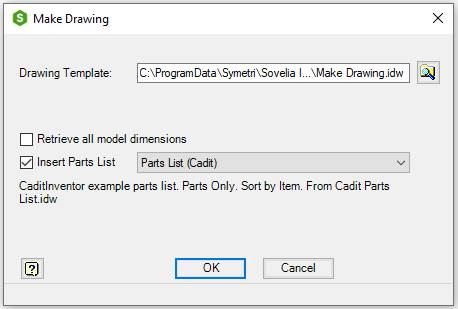
Make a drawing of the current component. Drawings are made from a selected idw or dwg template.
It is possible to retrieve the dimensions from the model and insert a Cadit parts list.ini when the new drawing is made.
It is also possible to configure Sovelia to copy model properties to the drawing or update scale property when the drawing is made.
Start from Assembly ribbon, Tools ribbon or 3D Model ribbon, on the Sovelia panel:

| Command | Value |
|---|---|
| Drawing Template | Name of an Inventor idw or Inventor dwg template for drawing creation. Default value is the previous value in the current assembly if the command has been used on the current assembly before. If not, it is the previous Template used by the command |
 |
Browse for a template |
| Retrieve all model dimensions | Check to get all model dimensions in the new drawing. The dimensions will be inserted arranged. It is not recommended for assemblies |
| Insert Parts List | Inserts selected Parts List in the new drawing |
| OK | Creates a new drawing |
| Cancel | Closes the dialog box |
Model properties are copied, and scale properties are updated automatically according to the settings in CaditInventor.ini
The new drawing is made according to certain rules which control number of views, scale, rotation, margins and gap between views. This is different for different component types.
The configuration file Cadit Make Drawing.ini contains values for the scale list, margins, gap, rotation and other settings.
The layout is according to this list:
| Component type | Criteria | Scale | Figure (click to Expand) |
|---|---|---|---|
| Sheet Metal Part, Flat Plate | Flat Sheet Metal parts. Property ct_cut_info has one of the following values: FPE1, FPEZ. | Scaled to fit all views in the border. Drawing base view from the flat pattern of the part. | 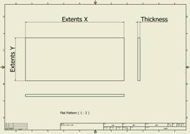 |
| Sheet Metal Part, Folded Plate or Folded Profile | All other Sheet Metal parts | Scaled to fit all views in the border. Drawing is divided in to, one half for the Flat Pattern and the other half for tree views of the folded model. | 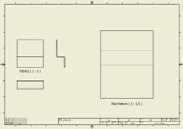 |
| Standard Part, Plate | Plates. Property ct_cut_info has one of the following values: PL, DPL, XY, XZ, YX, YZ, ZX, ZY, TXY, TXZ, TYX, TYZ, TZX, TZY, PXY, PXZ, PYX, PYZ, PZX, PZY. | Scaled to fit all views in the border. Base view orientation is aligned with the drawing border | 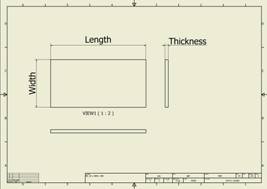 |
| Standard Part, Profile | Cut-length profiles, beams, yard goods. Property ct_cut_info has one of the following values: X, Y, Z, L, FPEL, RB. Frame generator or content center beams with property G_L or pipes with property PL | Scaled according to width of section view. User can manually break view to adjust the length | 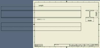 |
| Standard Part | All other parts | Scaled to fit all views in the border. Standard view orientation | 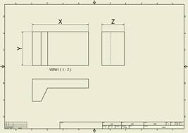 |
See also Cadit Make Drawing.ini, Cadit parts list.ini, Property editor, CaditInventor.ini, File name setup, Open common folder, Open local folder and Open user folder.