General Information
Pressure Drop Calculations have been implemented in Swedish Sovelia Plant Template Projects. This functionality calculates pressure drop for each component in a line, and these individual figures can be summarized for each pipeline and presented in the report.
Pressure Drop Calculations are not applicable for branched lines. The calculation is most accurate for liquids, as the formula does not account for gas expansion.
Setting up Pressure Drop Calculation
For the Pressure Drop Calculation to work, lines must have tags. Additionally, all fields in the picture above require values.
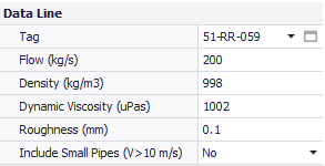
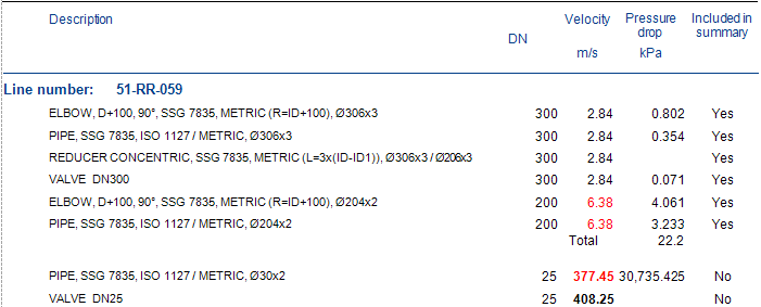
If Include Small Pipes is set to “No”, the calculations will not include pipes with velocities above 10 m/s.
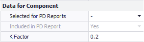
The K-factor should be set for all components (Tees reducers and elbows have a default value of 0.2).
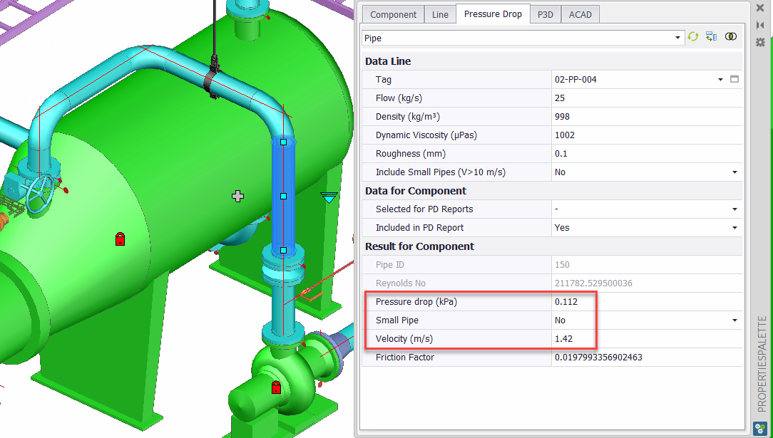
A component can be excluded from the pressure drop report by setting Selected for PD Reports to “No”. If Selected for PD Reports is set to “– “ (null) and the velocity is above 10 m/s, the component will automatically be excluded from report if include Small Pipes is set to No.
The available options for valves are Kv, Cv or K-factor.
Reports
Four different reports have been created:
1. Naviate P3D Pressure – Check calculation
2. Naviate P3D Pressure Drop by Component
3. Naviate P3D Pressure Drop by Linenumber part category
4. Naviate P3D Pressure Drop by Linenumber
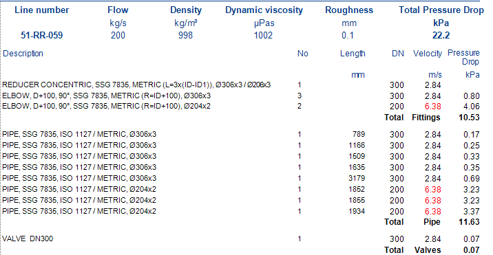
In the Check Calculations report all components are presented, and the user can easily see which components are included in the reports.
The By Component report presents the pressure drop for all included components.