Edit properties on parts, assemblies and drawings
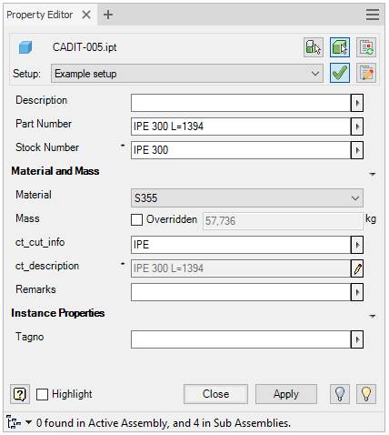
Property Editor is used to edit properties in part files, presentation files, assembly files, parts, sub-assemblies and virtual components in assembly files and title blocks and sketched symbols in drawing files. The dialog can have different setup for different file types.
The Update properties command will run automatically on the destination part with its current settings.
Start from Assembly ribbon, Model ribbon, Sheet Metal ribbon, Manage ribbon, Place Views ribbon or Annotate ribbon, on the Sovelia panel:
![]()
Keyboard shortcut Ctrl+Q also starts and stops the Property Editor.
The Property Editor dialog can be open and accessible while you work. The dialogue can be docked in the browser or to the right or left of the graphics window.
It may be necessary to manually refresh the contents of the dialog if the component's properties are changed by another function.

| Command | Value |
|---|---|
| Setup and selection | Selection settings, refresh contents or change setup |
 Icon showing edited component type Icon showing edited component type |
The name of the current component being edited or number of components selected if more than one. A tooltip shows the names if more than one part is selected. To edit the main assembly, select it in the browser or by deselect other components |
 Select component priority Select component priority |
Select component to be edited. The selection is in component priority mode. Only first level components, parts or subassemblies are found if selected in the graphics window |
 Select part priority Select part priority |
Select part to be edited. The selection is in part priority mode. Only parts are found if selected in the graphics window. If multiple components are selected, all selected parts appear in the edit fields. If the property values are different, the text * VARIES* is shown in the edit field and the color of the field changes to light yellow. If multiple components of different component type are selected, only common properties will be displayed and editable. |
 Re-read properties from file Re-read properties from file |
Re-read property values from the edited file. Manual refresh might be necessary if changed by another function when Property Editor dialog is open. |
| Setup: | Select Assembly Setup, Modeling Setup, Drawing Layout Setup or other setup, depending on the edited file type. Select setup for current file type in the list. Each file type has its own setup. Assembly Setup is for assembly files, Modeling Setup is for part files and Drawing Layout Setup is for drawing files. It is also possible to configure other setup types, for example Sheet Metal Files, Weld or MyCustom. Therefore, the setup is different for each file type even if it has the same name. Each file type has its own set of system default setup. Their names are in brackets and cannot be changed or saved. |
| --- | System default setup for Assembly files: |
| --- | < |
| --- | < |
| --- | System default setup for Modeling files: |
| --- | < |
| --- | < |
| --- | System default setup for Drawing Layout files: |
| --- | < |
| --- | < |
| --- | < |
| --- | < |
 Set selected setup as Standard Set selected setup as Standard |
Select current setup to be default for current file type. The button is on for the default setup and off for the others. |
 Property Editor Setup Property Editor Setup |
Opens the** Property editor setup** dialog |
| Contents from the selected component or components | List of properties according to current setup. Instance properties and parameters can also be edited. Properties may have rules that must be followed otherwise a warning icon will appear. Values can be selected from drop-down lists, if present. If a field is a list only drop-down field, a value must be selected from the list. Fields between headings can be collapsed or expanded |
| Headings | Groups of properties can be organized under headings. Fields between headings can be hidden or expanded by clicking the heading |
| Standard property edit fields | Change the values in the edit field. Use right click menu to cut, copy, paste, delete, insert expression, or insert recent values. |
| Drop-down field | Change the value by typing in the field or select from the drop-down list |
| List only drop-down field | Change the value by selecting from the drop-down list. |
| Disabled property edit fields | Shows the value for the property in a disabled edit field |
| Result property edit fields | Shows the value of a property generated by Update properties. The source of this property might be other properties or calculated values |
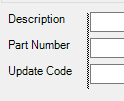
| ct_cut_info / Update Code | Code used by Update properties. Change the values in the edit field. Use right click menu to list the most common codes. The more option shows more codes. The codes are listed with a hint. Read more under ct_cut_info codes |
| Material Category | Filters the material property to categories. Select material category in the list |
| Material | List current document materials. Select material in the list |
| Mass | Shows the mass property. The mass is calculated from the volume and the density of the material. Check the Overridden checkbox to type in the mass. The calculated mass use the precision from “Linear Dim Display Precision” in Modeling Dimension Display under Units in Document Settings |
| Overridden | Check to override the calculated mass and type in new mass in the edit field |
Splitter  |
Drag the splitter to change the width of the edit fields and the field description |
 Right click Right click |
Shows the Right click menu with options to fill in the edit fields |
 Expression icon Expression icon |
The field has and Expression and additional options to the right click menu |
| * Star tooltip icon | The field has special formatting or mandatory rules, such as minimum or maximum number of characters, forced uppercase or lowercase letters or list only values. A tooltip on the icon shows which formatting that applies. The letter case updates automatically if the property has a case formatting |
 Warning icon Warning icon |
The field has a value that not are compliant with the special formatting or mandatory rules set for that property. A tooltip on the icon shows more information about the formatting or rules for the property |
 Help Help |
Starts the help topic for this dialog |
 |
Check to highlight all appearances of the selected component in the graphics wind |
 View Representation View Representation |
Activate selected view representation |
 Visibility off Visibility off |
Turns off the visibility for the selected components. The visibility state is stored in the view representation called Property Editor |
 Visibility on Visibility on |
Turns on the visibility for the selected components. The visibility state is stored in the view representation called Property Editor |
| OK | Save changes, update properties and closes the dialog box. The properties are updated with the current settings of the Update properties command |
| Cancel | Closes the dialog box. Changes made, but not applied is discarded |
| Apply | Apply changes and update properties. The properties are updated with the current settings of the Update properties command |
| Information field in the lower part of the dialog | The field in the lower part of the dialog shows information about the selected components and the workflow |
To create drop down lists or set rules to properties see Cadit property editor.ini
See also Update properties, Property editor setup and ct_cut_info
