
Background
The Set Properties tool allows CAD managers and administrators to enforce compliance for file properties in Inventor. While there are other ways of quickly entering iProperties in Inventor, such as iLogic forms, this tool provides a more robust solution for standardisation for larger organisations, or companies keen to reduce errors in their documentation. It also provides several features that are not available with other methods, such as the ability to toggle between model and drawing iProperties in a drawing file.
Included Options for Admin
- Customize which iProperties are necessary for drawings (dwg/idw), parts, assemblies and presentation files respectively.
- Mandatory and non-mandatory properties.
- Force-to-uppercase.
- Read-only properties.
- Fixed and editable multi-value lists for any property.
- Default values for any property.
- Customizable tabs.
- Maximum character entry.
- Automatic trimming of leading and trailing spaces.
- Easy entry of date information for checking.
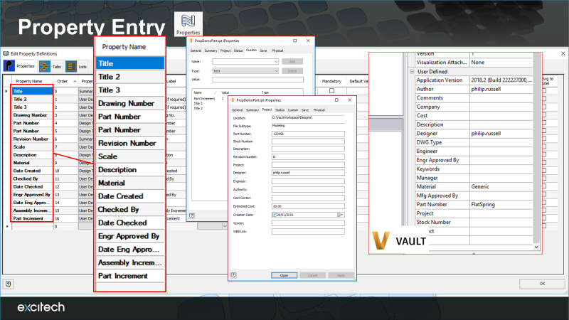
- Option to specify any iProperties you wish to be automatically copied from an Inventor model document (part/assembly/presentation) into the drawing document that references it. This is particularly useful for Vault, as it allows drawings to be searchable using the same metadata as their referenced models where desired. Note this capability is different from the standard Inventor ability to reference model iProperties on a drawing border, which doesn’t create matching properties in the drawing document.
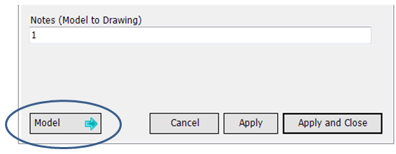
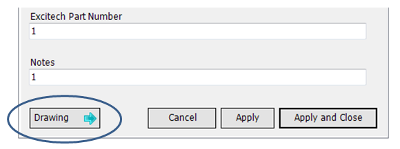
- Easy access to directly edit referenced model (part/assembly/presentation) iProperties dynamically while within a parent drawing – no need to open the model file separately to edit the properties. The user can conveniently toggle between the active drawing properties and the referenced model properties (for the first drawing view on the active drawing sheet) as shown below.
Configuring the Tool
The goal in configuring the tool is to create a data entry form for the properties you and your department need to track and display in your drawing title blocks.
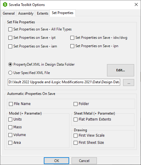
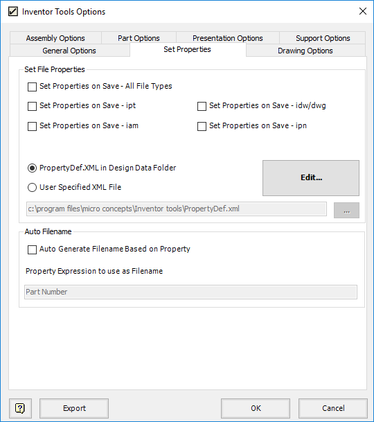
- To start, find the Sovelia Toolkit Options button and click to access the options dialogue.
- Find the properties tab and hit the Edit button.
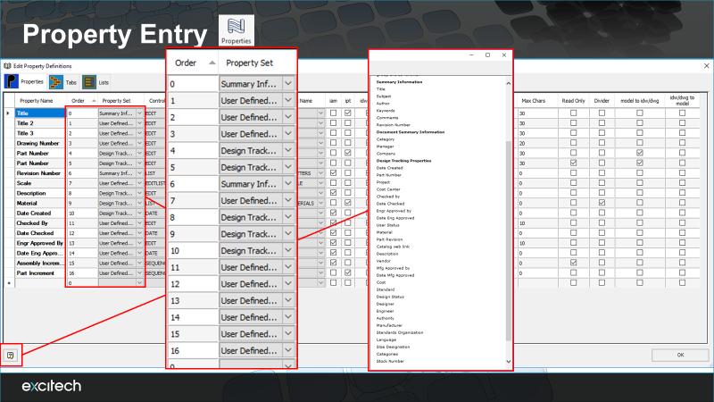
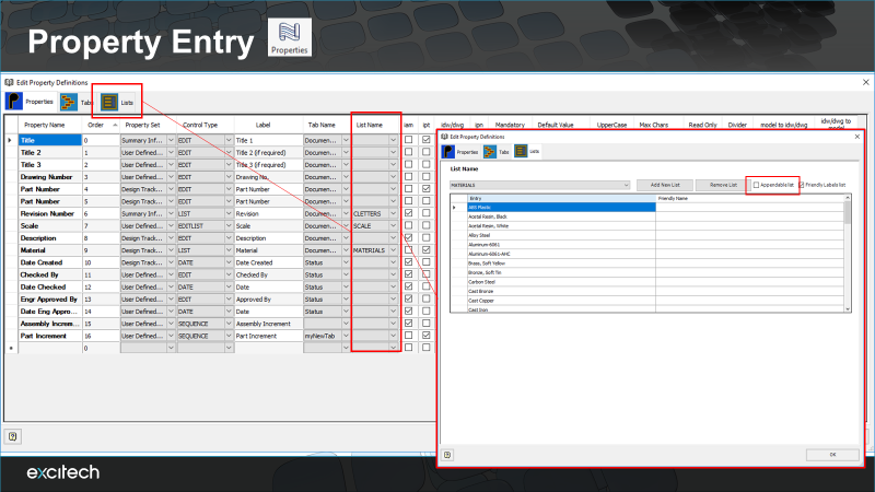
3. This opens the properties editor. Looks like a lot at first but is quite simple to configure.
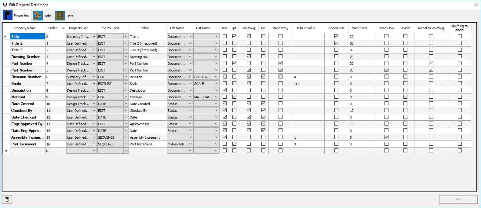
4. First Column is the property name. This is what will appear when interacting with the property outside of the properties dialogue you design i.e. in the Inventor iProperties menu, Vault, when you’re creating mappings for title blocks etc.
5. Columns two and three are Order and Property set. Order you use to control the list, simply overwrite the values to move up or down. If a property is above another in the list, it will be above on the form produced.
Behind the scenes Inventor groups properties into different sets, these sets do not correlate to the tabs in the inventor iProperties form. If you are creating your own properties, then set to “User Defined”. If using an existing property, then hit the help button and go to ‘reference’ to look up which group is correct for the property you are after.
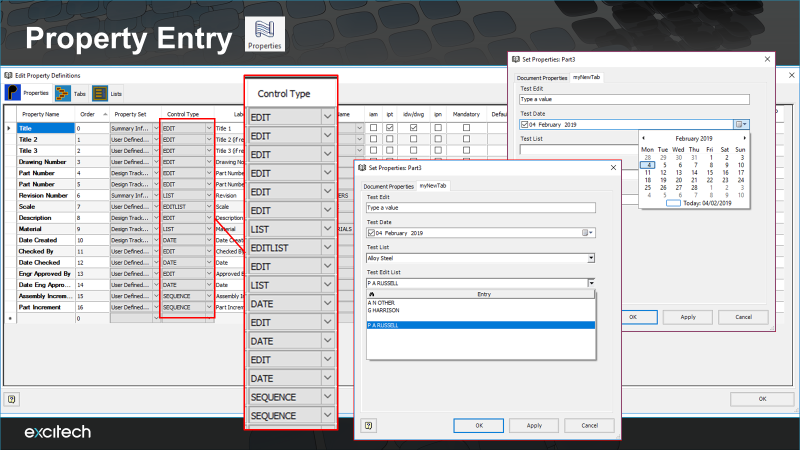
6. Control Type column allows different types of data entry.
Edit = Simple Text Field
Date = Date selection dialogue box
List = Drop down list of predefined options
Edit List = Drop down list with the ability to type text if none of the predefined options are appropriate. Optionally, have the list remember unique manual entries for later selection.
Sequence = Seed with a default numerical value and it will increment on property update
7. Columns five and six, are what the property will be labelled on the form. E.g. you may want to enter part number property name twice and label one to assembly number on the assembly properties form for clarity.
Tab name is which tab you would like the property to appear on. To edit tabs, go to the Tabs option.
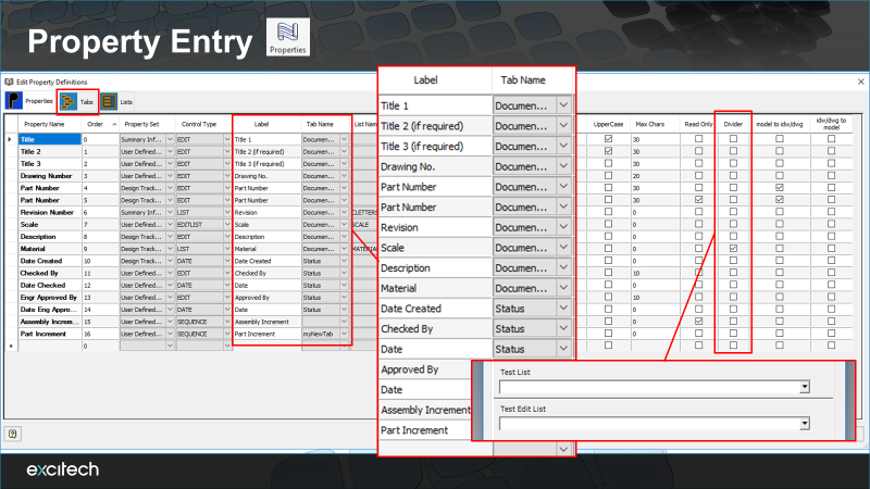
8. If you have properties using the list or edit list entry type, you will need to select which list you would like to use with the property. These are configured in the lists tab. The appendable tick box applies to edit list entries only and sets if the list will collect unique manual entries. Suggested property “Author”
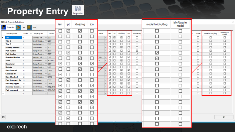
9. Highlighted farthest left is the file type cluster. Although a property is in the list, it isn’t going to do anything till it is assigned to a file type. Tick the box where you want to see a property on a form.
NOTE: Although it is possible to put things like “part number” in every file type, users are advised that simple implementations are normally the most successful, and it is advised to reference the properties in the model directly in the title block.
On the right is the copy options, if it is necessary to keep a property in two locations and synchronize, these tick boxes control the flow of data.
Manditory = To allow properties to be updated these entries must be completed. If set to update properties on document save, manditory entries must have been entered before the file can be created.
Read only = This allows a property to be displayed for reference. Examples of when this might be useful are displaying the output of physic properties, properties that are the product of a formula, values that should be checked before drawing/design sign off.
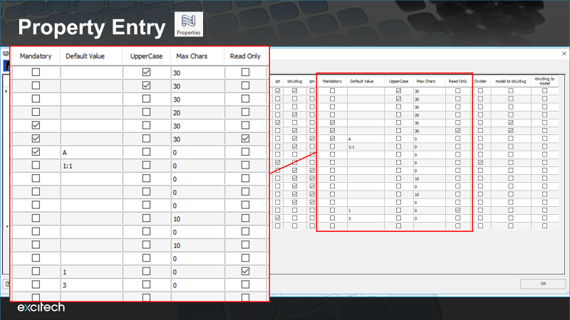
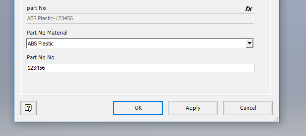
10. Formula can be entered in the cells, normally most useful as a default value for a property. In the example below we are combining two types of property entry to create a part number.

The format for a formula cells follows Inventor defaults. Put an = at the beginning and any properties you want to reference between < >. If you are populating a default value with a formula, to test you will have to create fresh .ipt .iam etc. files each time, as once a property is written to default values will not be applied.
The remaining options to look at are when the dialogue will be triggered and where to store all the customisations.
If set to update properties on save the dialogue will appear and require all mandatory fields to be completed before saving a file.
The “PropertyDef.xml” file stores all the customisations you have made. By default, a file is created in the “Design Data” folder where many of Inventor settings and resources are kept.
If you already sharing a design data folder with your team then changes made will automatically appear on other workstations.
If you are not sharing your design data folder then it may be necessary to copy your local version on to a shared location and point other workstation to the file using the “User Specified XML File” option.
Using the Tool
The properties dialog can be set by your admin to appear if there are missing values in important iProperties. Depending on their preference, the prompted entry can appear when mandatory fields are blank, when any fields are blank, or not at all.
Once the required fields in the form have been entered, the form will no longer appear when saving a file in Inventor.
The user has the option at any point to view the property dialog by hitting the ‘Properties’ button. This is accessible in the Part, Assembly, Presentation and Drawing environments in the Sovelia toolkit tab.

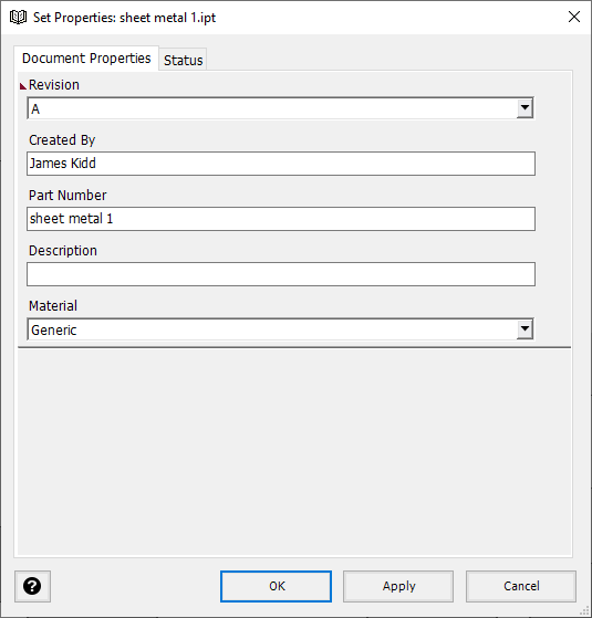
Note: iProperties that have been specified as ‘mandatory’ by your CAD admin will have an asterisk ‘*’.