
About The Sheet Selection Box
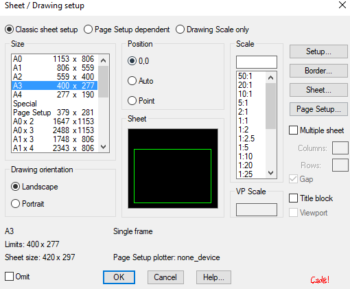
In the "Sheet Selection" dialog box, the sheet format and scale are determined. Drawing area and which frame configuration is selected are displayed at the bottom of the box. If the drawing has a frame already, information about this will also be displayed.
The user's previous sheet selection will be suggested each time the program is run.
Sheet selection program can be started automatically every time one enters a drawing where the frame is not inserted. If desired, this can be turned on/off in Startup Settings.
Set scale and drawing limits
Starting from the menu "Start -> Sheet"
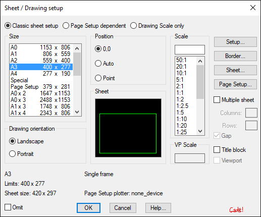
Classic sheet selection: Allows you to choose the size, drawing orientation and scale regardless of what is specified in Page Setup.
Page Setup Dependent: Size and drawing orientation are determined in Page Setup.
Drawing Scale Only: If you only want to change the scale
Size: Choose from A4, A3, A2, A1, A0, Spesial, or Margins. Special format is selected as the frame is inserted. Margins provide a frame size adapted to the sheet size selected in Page Setup. The other frame sizes are set under Frame.
Position:
-
0.0 The sheet is placed in 0.0.
-
Auto Sheet is automatically placed so that the center of gravity on the sheet and drawing
-
Point User points where to place the sheet
Drawing orientation: Select whether the sheet is Landscape or Portrait.
Scale: Enter the desired scale or select in the list.
Omit: The sheet selection program starts automatically in drawings without a frame. If you do not want to insert any frame, nor do you want the sheet selection program to start automatically the next time one enters the drawing, one of the Exclude and exits the Sheet Selection dialog with OK.
Title Block: Check to insert title fields. Title fields are inserted with the TITLE FIELD application.
Setup
During setup, the frame is determined, as well as some other parameters.
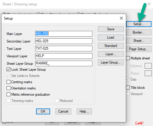
Main layer
Layer name for the main geometry of the frame.
Seconday Layer
Layer name for other geometry on the frame.
Text Layer
Layer name for text
Sheet Layer Group
Enter the layer group name on which the frame will be drawn. If objects have already been drawn on the specified layer group, the program will ask whether these objects should be deleted when inserting a new frame. Thus, one can delete the old frame when inserting a new one. It is important to keep in mind that all other objects drawn to this layer group will also be deleted, therefore select a unique layer group name.
If no layer group name is entered, the frame will be inserted without a layer group name and nothing will be deleted.
Lock sheet layer group
Specify whether the layer group should be locked. One advantage of the locked layer group is that one avoids deleting or moving the frame unwittingly.
Set limits to Extents
Sets limits to the outer limits of the frame, or the points selected when the frame is created.
Centering marks
Inserts centering marks according to NS 2400 section 7.
Orientation marks
Inserts orientation marks according to NS 2400 section 8.
Metric reference graduation
Inserts metric reference scale according to NS 2400 section 9.
Trimming Marks
Inserts marks for cleaning according to NS 2400 section 11.
Reduced
Inserts reduced marks for clean cutting according to NS 2400 section 11.
Save
Saves the layout of the project catalog. The layout is saved in a file that is named SheetValg.dbl and that is added to the project directory.
Download
Retrieves the project layout from the Sheet Selection.dbl file in the project directory. If the project setup does not exist, the default setup is retrieved.
Standard
Retrieves the default layout.
Layer
Starts the dialog to select layers.
Layer Group
Starts the dialog to select the layer group.
Border Size
**In the Frame Sizes dialog box, the size of the frames to be inserted is determined. **
The paper size appears next to it. For the frame size, consideration must be given to the margin sizes the plotter requires.
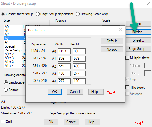
A0, A1, A2, A3, A4
Specify the width and height of the different formats.
Standard
Set standard framesizes
Norsok
Set Framesize according to NORSOK Z-005. Ask us about adding your standards.
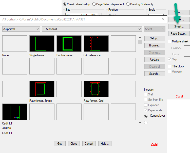
Sheet
By pressing the Sheet button, the dialog is started to retrieve and save sheet frames. This is the same dialog as for Symbol.
- Choose between standard and custom frames.
- Save own sheets
To save a sheet, do the following:
- Start with a default frame for the sheet format to be created. The size of this frame is adapted to the plotter, so that if drawn outside it can cause problems when plotting.
- Then draw the new sheet as it should be with any title field, etc. The default frame can be deleted if desired.
- Enter THE SHEET SELECTION on the page the sheet should be saved and press the change button.
Remember to choose the same format as it was based on. - Set up the Insertion points
-Specify base insertion point <0,0,0>: Select a point or enter for 0.0,0.
-Specify the lower left point <0.0>: Select a point or enter to get the same point as the base insertion point.
-Specify the upper right point: Select a point.
-Select objects: Then select the objects that will be included in the sheet block, and then zoom in the image to display in the dialog box.
The different sheet blocks are named after the format and by which number they are in the dialog box. A landscape A1 sheet can thus be named A1Li0101, while a standing A4 sheet can be named A4St0101.
If the sheet frame contains blocks of attributes, these will be stored in a separate file with the addition _a in the name.
In addition to the DWG file, an SLD file, with the same name, is created, which is used for the image in the dialog box.
Programmed Sheets
If there are special requests for the insertion, an AutoLISP file with the same name as the sheet block can be made. The file must be placed in the same directory as the sheet block and given the same name as it.
Example for landscape common A3 sheet number 2:
For example, LSP may look like this:
(princ "\nSetter inn liggende A3 ark nummer 2...")
(command "insert" "*t:\ct-ark\a3l-eg02" "0,0" (getvar "USERR1") "")
(setvar "ATTREQ" 1)
(setvar "ATTDIA" 1)
(command "insert" "t:\ct-ark\ttft1" (list (nth 0 (getvar "LIMMAX")) 0)
(getvar "USERR1") "" ""
)
(setq dvart 1)
(princ "\nOK.")
(prin1)
:::
(princ "\nSetter inn liggende A3 ark nummer 2...")
(command "insert" "*t:\ct-ark\a3l-eg02" "0,0" (getvar "USERR1") "")
(setvar "ATTREQ" 1)
(setvar "ATTDIA" 1)
(command "insert" "t:\ct-ark\ttft1" (list (nth 0 (getvar "LIMMAX")) 0)
(getvar "USERR1") "" ""
)
(setq dvart 1)
(princ "\nOK.")
(prin1)
The program inserts the sheet with the file name A3L-EG02. DWG from the T:\CT-ARK directory in the coordinate 0.0 and with the correct scale. The block is inserted exploded in and with * character. Additionally, the title field T:\CT-ARK\TTFT1 is inserted into the lower corner of the sheet.