
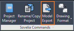
The Sovelia Commands group contains powerful functions for managing projects.
Project Manager
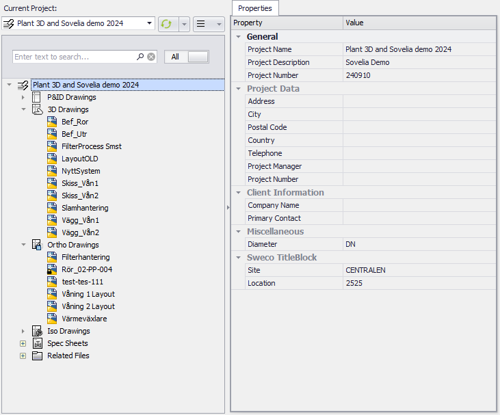
Selecting the Project Manager command opens a window that displays the current project.
Here, users can edit some of the project properties without navigating to the project setup. It also provides a quicker overview of each drawing’s properties.
Rename/Copy Project
As the name suggests, Rename/Copy Project allows users to rename projects, something which is not recommended in standard Plant 3D due to limitations in the program.
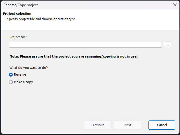
It also serves an important function when copying projects. The command copies custom folders and settings that are not copied with the standard Plant 3D project manager. Another example: when starting a project with the intention of using Sovelia Plant functions it is crucial that the project is a copy of a Sovelia template project. Using the Rename/Copy Project function is an easy way of making said copy, ensuring all critical files are present in the new project.
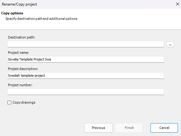
Choosing Make a copy, selecting the template project to be copied and clicking “next” opens the next window. Here the new projects destination, name, description, and project number can be chosen. There is also the option of copying over any existing drawings from the project.
Model Export
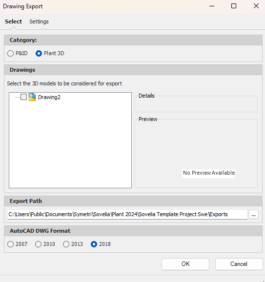
The Model Export command provides many new options when exporting a model. Clicking on the command opens a window where the drawing in question can be selected from either Plant 3D or P&ID. Users can choose an export path as well as which AutoCAD format to use for the export.
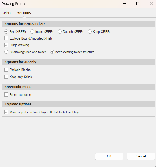
The Settings tab provides further customizability, such as options for what to do with any “XREFs” in the drawing, or how to handle 3D models. There is also an option to have the export occur in the background. In the program this is called “silent execution” and enables users to continue working while the export is running.
Drawing Format
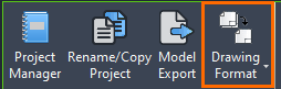
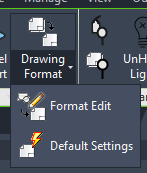
The Drawing Format function allows for easy editing of drawing borders and title blocks. With the Format Edit command supplementary blocks can be added. The Default Settings command sets drawing variables like “attdia”, “proxygraphics” and “filedia” to default values.
The Drawing Format Manager allows for updates and changes to drawing frames and headers on the fly while working with various P&ID and Ortho drawings.
Paper Format: Drawing frame size and layout size.
Title block: Title block.
Scale: Viewport scale.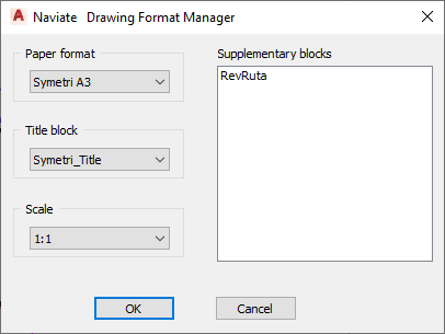
By clicking the down arrow and chosing format edit supplementary blocks can be added after the size and title block have been chosen.The system can be set up with multiple options of supplementary blocks.
Drawing Format Manager Setup
Overview
When setting up a custom Drawing Format Manager-setup there are a few things to keep in mind.
The settings-file the file NVFormatManager.ini controls where the Drawing Format function looks for its assets is located in the following path: C:\Users\Public\Documents\Symetri\Sovelia\Plant 2026\Sovelia Common Files\Settings 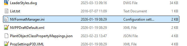
The assets are located in the following path: C:\Users\Public\Documents\Symetri\Sovelia\Plant 2026\Sovelia Common Files\DrawingFormats
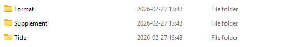
Three folders under this path contain the three types of assets that the function uses: multiple sizes of borders, the firm specific title blocks, as well as potential supplementary blocks like revision tables etc.

One method for changing the Symetri default templates is to open up the files and make changes or replace blocks within the .dwg-file. This method means there is no need to make adjustments in the settings file, but the files will also retain their original names.
The other method is to replace the Symetri template files, or create new ones.
Create custom assets
When creating new .dwg templates to use with the Drawing Format function, there are a few things to keep in mind.
The file needs to be saved in its exploded state to function properly:
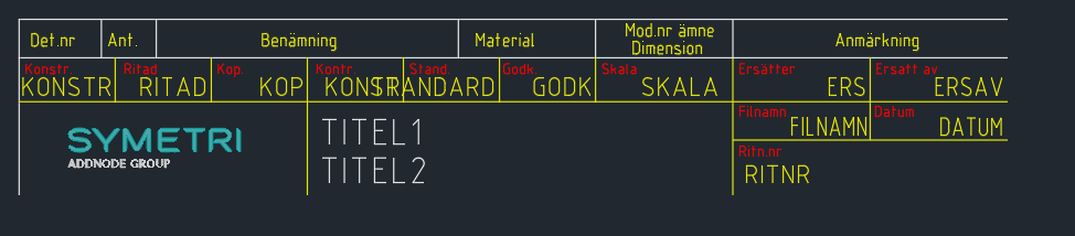
Also keep in mind where the block is placed in relation to the origin. The origin point is typically the lower left corner of the drawing, so the title block should be placed an appropriate distance to the right of the origin. As a rule of thumb, position the blocks in the same position as in the default templates provided by Symetri, and adjustments can be set up in the settings file.
Settings File
In the following section of the file we can see some default settings for file paths etc: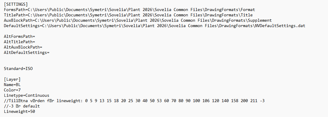
File paths can be edited based on need. The following section contains the default settings which control the title block-files:
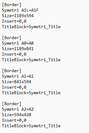
If using custom blocks the settings-file needs to be adapted with the correct file names. The text below serves as a template for how to adjust the code.
[Border]
My_Border_A3_Swe=My_Border_A3_Swe
Size=420x297
Insert=0,0
TitleBlock=My_Title_Block
[Border]
My_Border_A2_Swe=My_Border_A2_Swe
Size=594x420
Insert=0,0
TitleBlock=My_Title_Block
[Border]
My_Border_A1_Swe=My_Border_A1_Swe
Size=841x594
Insert=0,0
TitleBlock=My_Title_Block
“My_Title_Block” is an exemple of the name of a custom title block file.
The next step is to change the TitleBlock and AuxiliaryBlock-sections. Keep in mind to use the correct block names. 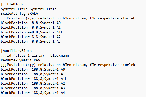
The following is an example of how to adapt the code for custom assets:
[TitleBlock]
My_Title_Block=My_Title_Block
scaleAttrTag=SKALA
;;;Position (x,y) relativt nh h rn ritram, f r respektive storlek
blockPosition=-188,8;My_Border_A1_Swe
blockPosition=-188,8;My_Border_A2_Swe
blockPosition=-188,8;My_Border_A3_Swe
[AuxiliaryBlock]
;;;Id (visas i lista) = blocknamndist
My_Rev=My_Rev
;;;Position (x;y) relativt nh h rn ritram, f r respektive storlek
blockPosition=-183,-3;My_Border_A1_Swe
blockPosition=-183,-3;My_Border_A2_Swe
blockPosition=-183,-3;My_Border_A3_Swe
Keep in mind the positions might need to be adjusted. The best method is to try out the Drawing Format Function, and measure the distance from the desired position in terms of the x and y axis, and adjust accordingly in the code.