Background
This tool allows quick placement of iCopy components into assemblies – it is an enhanced version of the standard Inventor iCopy tool.
While the standard Inventor iCopy tool is very powerful - allowing ‘stretchable’ assemblies to be placed into a layout using a ‘pick and place’ method - it is less suited to larger layouts, as each placement operation requires the iCopy template ‘copy or reuse’ options to be re-specified, and the file naming convention to be re-specified. The standard iCopy tool also does not allow a chosen Level of Detail (LOD) or View Representation of an iCopy template to be placed, only the ‘Master’ LOD and View Representation. Placing dozens or hundreds of iCopy assemblies can therefore be somewhat time-consuming and tedious.
This tool allows the previously listed selections to be made once, and then reused for multiple placements. Once the file naming convention has been specified, the filenames of the copied parts/assemblies are automatically incremented, and the files placed in the specified folder structure automatically. This tool also allows multiple instances of an iCopy template to be placed into a layout in one automated operation, based on a grid of work points, similar to placing a pattern of components, but with independent adaptive components allowing for irregular spacing and sizing.
iCopy is one of the more advanced tools in Inventor, as it involves adaptive parts and a type of skeletal modelling (using a derived master part). It is worth investing time to understand the above concepts (using the links below) in a traditional iCopy workflow, before introducing this tool to improve productivity. This tool can be used with any existing iCopy templates.
Preparing to use this Tool
1. Learn iCopy
It is strongly recommended that any users of this tool first become familiar with the standard iCopy tool in Inventor. Resources for this can be found here:
2. Design your iCopy Templates
This tool is designed to work with Inventor assemblies that have already been authored for use as iCopy templates. This means the iCopy template will contain the following elements:
- A ‘master’ or ‘skeleton’ part, which is adaptive. We will be referring to this part as the master part for the rest of this document.
- Parts which depend on the master part for their size. The master part will be ‘derived’ into each of these so it can be referenced.
- Library/standard parts that do not depend on the master part in any way (optional).
- Any iLogic rules defining how the assembly behaves as it is resized/configured (optional).
- Important. This tool requires that you add at least 3 work points into the master part and make them visible. These work points are the points that the user will select when placing, and they will be used to size and constrain the template into the top-level layout assembly. Note this requirement is specific to the Sovelia tool – it is not a standard iCopy requirement.
3. Test your iCopy Templates
This step is not strictly required; however it is strongly recommended that you ‘flex’ and test your iCopy templates using the standard Inventor iCopy tools. This will ensure that they resize correctly when placed into a top-level layout assembly, and that they can handle all the required shape variations that they may encounter without error. Please follow the method detailed in the AUGI article above.
4. Publish your iCopy Templates
The Sovelia tool does not actually require the iCopy template to be published/authored for use with Inventor iCopy, but it is advisable for the reasons above. If it has been published/authored, it can then be used for either the standard Inventor iCopy placement tool, or the Sovelia iCopy tool, depending on the user’s preference.
Congratulations – you are now ready to use the tool!
Using this Tool

Single iCopy
Use this tool in the following scenarios:
- Irregularly positioned components (e.g. no recognizable ‘columns’ or ‘rows’ are required.
- Components follow a curved or irregular route.
- Many components are not on the same plane – they are angled with respect to each other.
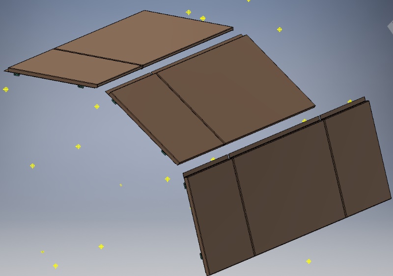
Process:
- You must be in an assembly file (normally a top-level or sub-level GA assembly) with a ‘grid’ part placed into it. This grid part must contain visible work points, as these are required to ‘anchor’ the iCopy template to. Note that normal edges and corners are not suitable for positioning an iCopy template, only work points.
- Hit the ‘Single iCopy’ button.
- Browse and select the iCopy template you wish to place. This must be an Inventor assembly file (.iam)
- Use the Copy / Reuse dialogue box to specify which components in the iCopy template you wish to be independently copied, and which you wish to reuse. Each line in the dialogue can be selected to toggle whether it is copied or reused. Typically, standard parts (fittings, fixings, brackets etc.) will be reused, as this enables the part to remain centrally controlled in a single library file. In the example below, the HOOK PLATE part is being ‘reused’ – this means that even if 300 iCopy templates are placed, they will all contain a reference to the same HOOK PLATE part file on the system.
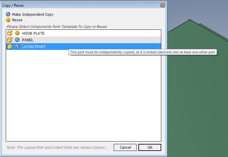
Note that the user is prevented from specifying to ‘reuse’ any parts in the iCopy template that reference the ‘skeleton’ master part in the iCopy template. These parts must be independently copied to allow them to resize independently of other placed iCopies in the assembly, depending on which work points the user chooses to place the template on to.
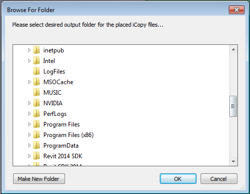
5. Specify the top-level output folder to save the copied files to. Note that this folder must be contained within the ‘umbrella’ of the currently active Inventor project file.
6. Choose the file naming for the copied parts. The Filename Suffix is optional. The copied iCopy templates will be saved in folders with automatically incremented folder names (e.g. for the below selection – the folders will be called ICOPY-1, ICOPY-2, ICOPY-3 etc.…). If a particular folder already exists on the local system, it will be skipped, and the next available folder name will be found. The tool will not delete any existing files on the system.
The purpose of the Project Number entry is to allow metadata searching by project number. Every independently copied file will be given a Project Number suffix. This can be entered simply as ‘1’ if desired.
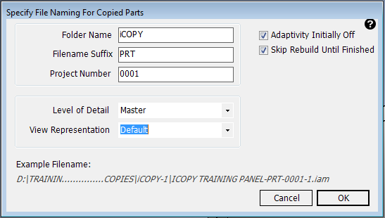
The Level of Detail (LOD) of the iCopy template can be selected. For example, if an LOD called ‘Simple’ is selected in this dialog, the ‘Simple’ LOD of the iCopy template will be placed into the top-level assembly. This can be useful for iCopy assemblies that rely on component suppression, as components cannot be suppressed in assemblies if you are in the ‘Master’ LOD.
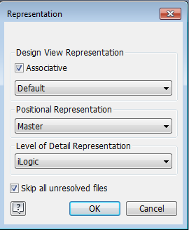
Likewise, the View Representation (View Rep) of the iCopy template can be selected. For example, if a View Rep called ‘Brackets Removed’ is selected in this dialog, the ‘Brackets Removed View Rep of the iCopy template will be placed into the top-level assembly. It will also be made associative (see image below). This can be useful for iCopy assemblies that may have some components hidden (invisible), as components cannot be made invisible in assemblies if you are in the ‘Master’ View Rep.
The two options above will automatically perform the same function as selecting a component in the Inventor assembly browser, right click -> Representation, choosing the Design View Representation, making it associative, and choosing the Level of Detail (LOD). See image below.
Adaptivity Initially Off – Explanation
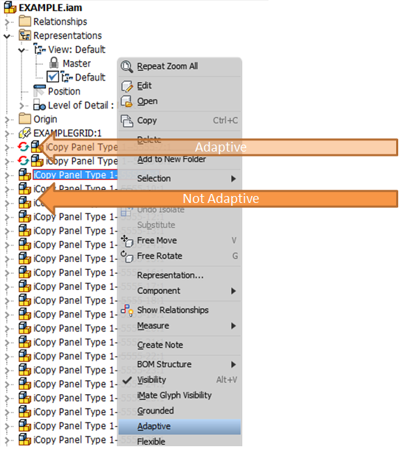
This should normally remain ticked as iCopy assemblies rely on adaptivity to function. This is what allows a template assembly to be placed on workpoints in a layout assembly and automatic resizing to take place. However, adaptivity is a resource-hungry function in Inventor, and Inventor is required to constantly check whether adaptive components need resizing (if the workpoints have moved). Therefore, assemblies containing hundreds of adaptive components will generally have poor performance in Inventor. Ticking this check box will prevent this problem by switching off adaptivity for each component as soon as it has been successfully placed and sized in the assembly. The user then needs to be aware that if the grid of controlling workpoints is moved or changed, then the constraints that ‘anchor’ the iCopy components will error unless adaptivity has been switched back on for the affected assemblies. This is simple – just right click on the affected assemblies in the Inventor browser and tick ‘Adaptive’ before making changes. Adaptivity can be switched off again afterwards if desired to preserve performance.
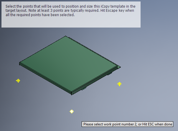
7. Select the work points to position the iCopy template. Note the workpoints must be already visible in the saved template. Remember the order of selection, as this will determine the order you need to pick the attachment points in the GA layout. When you’ve finished selecting points hit the escape key to move on.
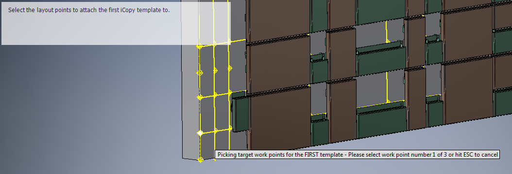
8. Select the work points in the GA layout to attach the template work points to. The order of selection is important. Once the required number of points have been selected you will move on automatically.
9. You can then continue selected groups of points to place further iCopy templates as desired. When you have placed all the required templates, hit the escape key to finish placement.
Multiple iCopy
Use this tool in the following scenario:
- You have recognizable ‘columns’ and/or ‘rows’ of components to be placed. They are located on one or more planar (flat) surfaces, and the orientation of the components is uniform.
Process:
The process for Multiple iCopy is initially identical to the Single iCopy method detailed above. Please follow steps 1-8 above, then steps 9 onwards below.
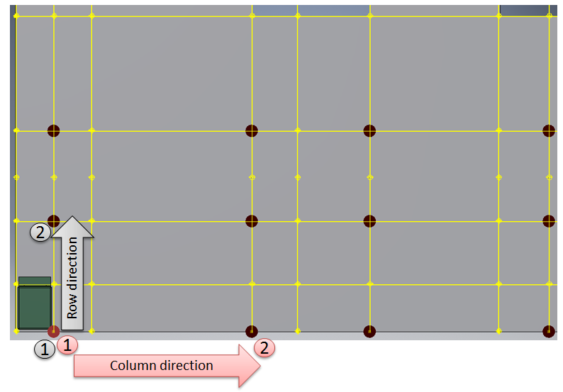
- We now need to define the ‘column’ direction for the iCopy template to be ‘arrayed’ or ‘patterned’ in. Follow the prompts on the screen to do this. You will need to pick the ‘base point’ or starting point for the column direction first, and then another point defining the move.
It is important that you pick the correct ‘base point’ for the patterning for predictable results. See the below examples showing the correct selection.
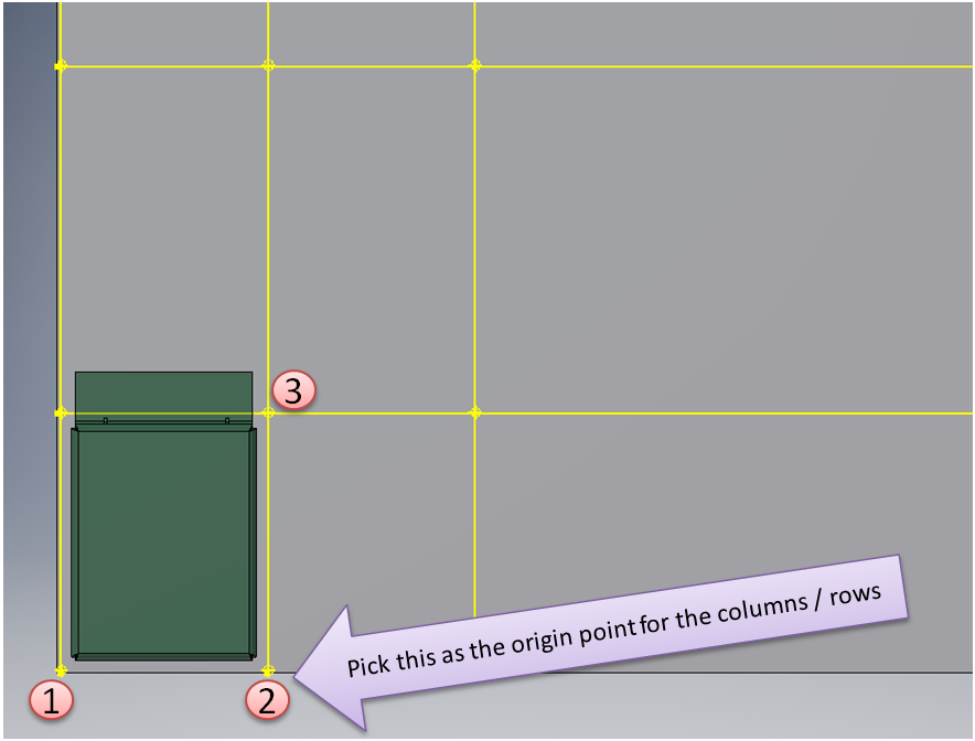
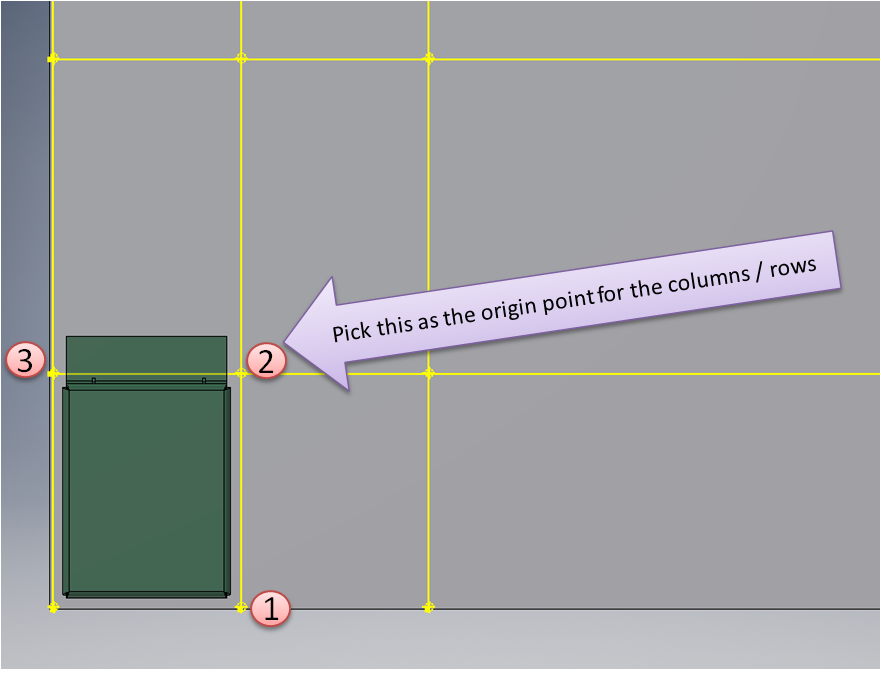
Note also that points can be ‘skipped’ if desired depending on the selection for the columns and rows (primary and secondary direction).
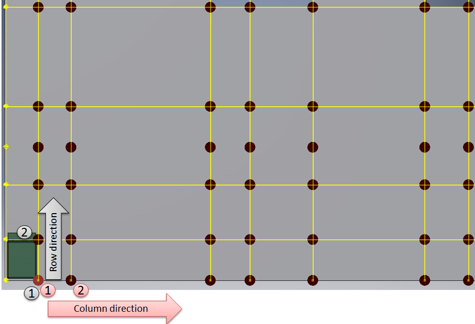
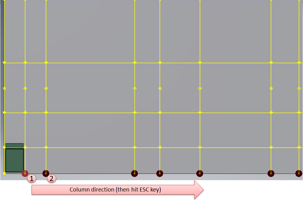
Note also that it is not necessary to pick a secondary direction – you can hit the escape key after picking a primary direction for the pattern.
Once the pattern directions have been selected, a preview of the components that will be placed is shown, allowing cancel or continue if desired.
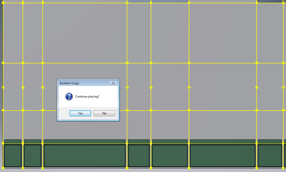
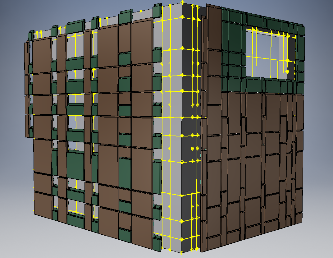
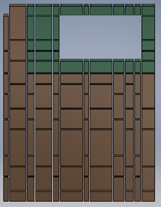
Once the pattern of components has been placed, a second pattern can be placed immediately using the same selections as previously. This can allow combinations of patterns and multiple rooms / walls to be populated as part of the same operation (e.g. as shown below).
Notes (FAQ)
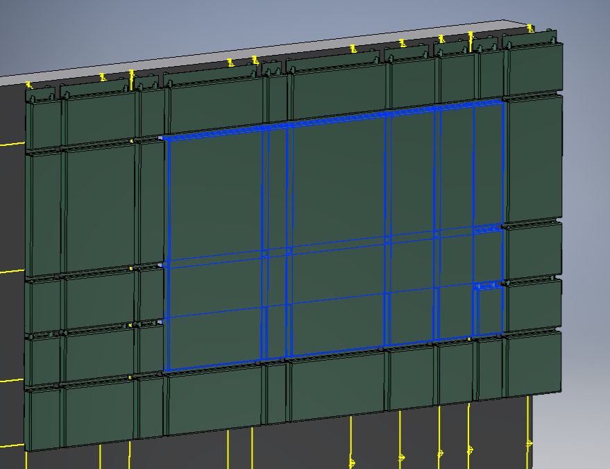
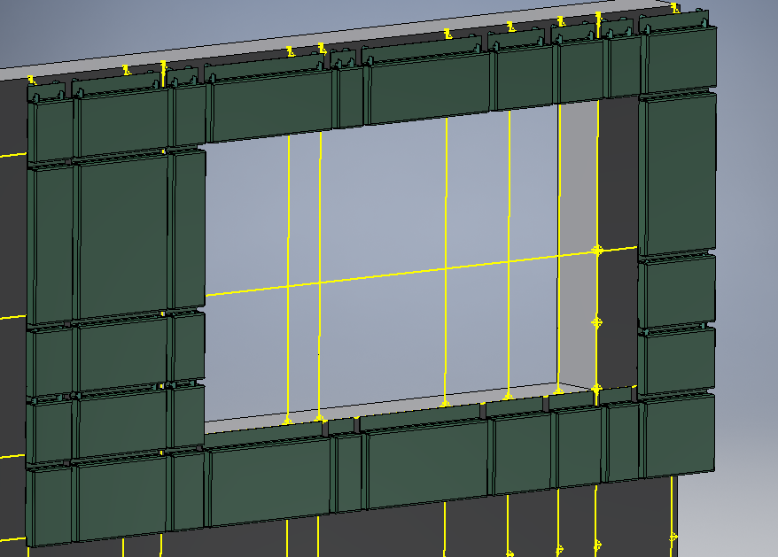
Q: How can I include cutouts/gaps in my grid layout (such as shown below), when using the ‘Multiple iCopy’ button.
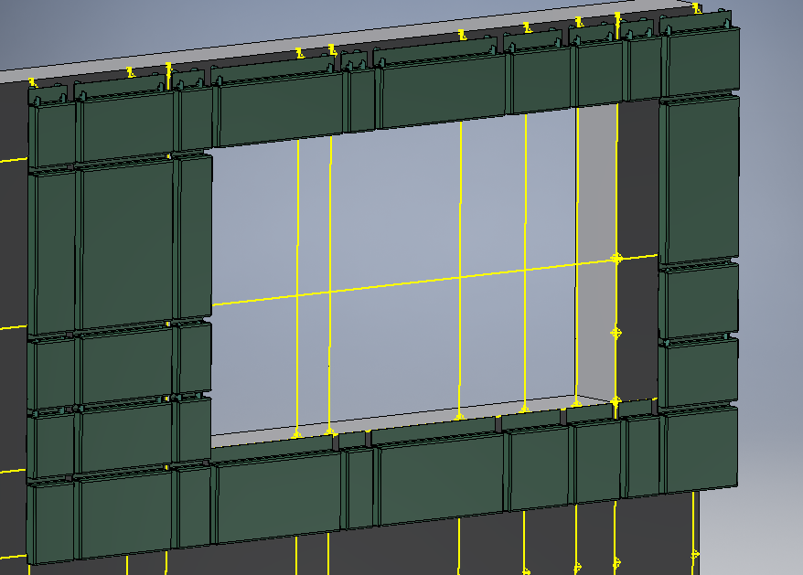
A: You can’t currently completely omit areas of a layout when placing. Two options are available:
- Simply place the components on all areas of the grid and delete the components in the area you don’t require afterwards.
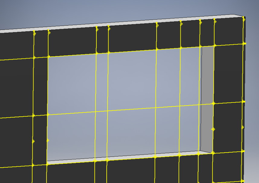
- Be aware that only visible workpoints will be recognised when placing – so if you want to omit any area of the layout, just switch off the visibility of the workpoints in this area before using the tool.
Important note 1: you need to switch off the visibility of the workpoints in the ‘workpoint grid’ part itself not from the assembly, and not when editing the workpoint grid part in the assembly context. This means you need to open the workpoint grid part in a separate window to edit the visibilities, otherwise the workpoints will still be recognised.
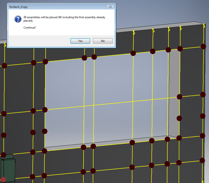
Important note 2: as shown below, this method will not completely omit the area when placing components, but will only place components across the gap, meaning the placement operation is much faster, and fewer components need deleting when the operation is finished. See the pictures below for explanation.
Q: Can I copy associated drawing files of iCopy assemblies using this tool?
A: No. The standard Inventor iCopy tool does allow drawing files to be included as part of the ‘deep’ copy operation. However, the Sovelia tool does not currently support this. The tool will recognise only Inventor assemblies and part files as part of the automated copy operation.
