Sovelia P&ID Tools give users access to advanced functionality for managing P&ID drawings in Plant 3D.
Coordinates
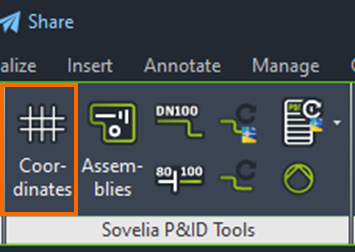
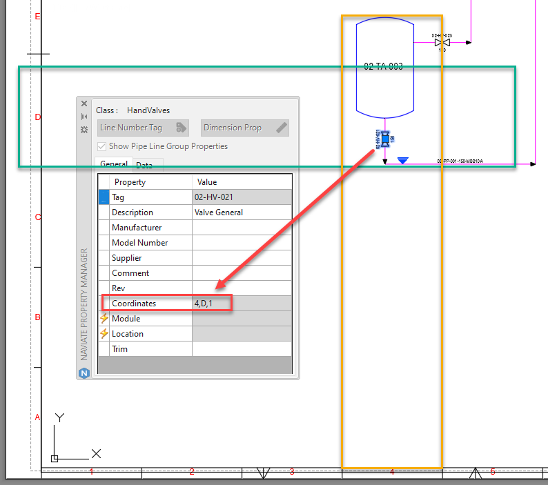
The Coordinates function lets the user store the drawing frame coordinates on P&ID objects. This allows for the creation of lists with drawing coordinates, making it easier to locate the object on the P&ID once it's exported to PDF or printed on paper.
Coordinates are listed in BOM.
When initially executing the command, the system will prompt you to add the necessary database fields to the current project. Drawing frames differ in terms of size and coordinate system. Therefore it is necessary to change the coordinate grid settings. This is done with the Coordinates function, or NVPETSETTINGS.
Coordinates Setup
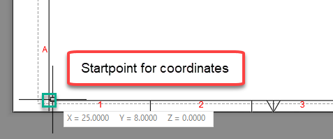
Open the drawing frame you want to use and measure the 0.0 location of your drawing's viewport.
Either right click on the current drawing or open NVPETSETTINGS and fill in the starting coordinates.
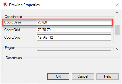
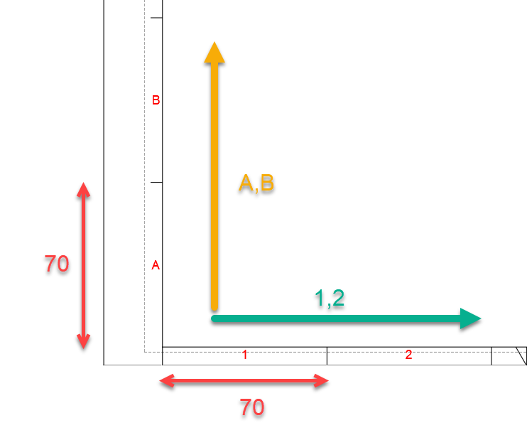
Measure the dimension of the grid and type it in to the coordinate settings, in this example 70,70
Now it’s time to decide the naming of the grid’s X & Y axis. This is done from left to right and bottom to top
X = 1,2
Y = A,B
Assembly
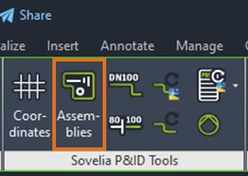
The Assembly command is used to group P&ID objects. All objects inside a closed polyline are designated to belong to the same assembly, and properties can be inherited based on assembly designation. The function is useful for managing properties like room or module number.
Assembly Setup
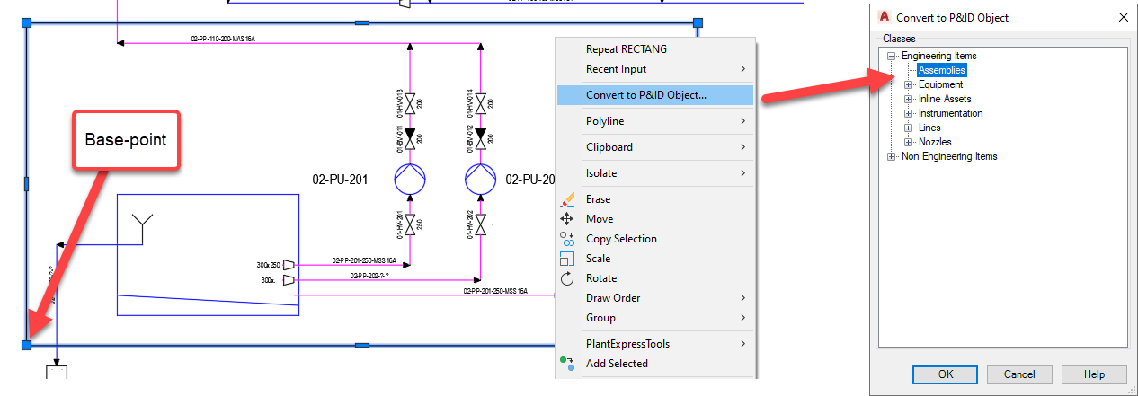
To create an Assembly, start by making an enclosure around the objects that will be in the same assembly, in this case a rectangle.
Convert it to a P&ID object and select Assembly from the list. Then specify the insert point.
Run the Assembly command to make sure all object on the drawings get the correct database fields.
To set the properties of the assembly, double click in the assembly frame, and set a Location and Module name. Example:
Location = PUMP-ROOM 2550
Module = FP200 (Filter pumps)
Select one of the components inside the assembly and notice the change on the component's location and module.
An assembly designation can be implemented to for example:
TAG-numbers
Description text
Or any database connected field
Update Line Annotations & Check Nozzles
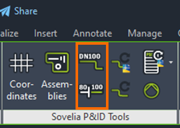
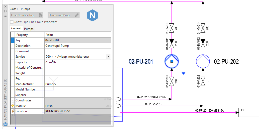
The Update Line Annotations and the Check Nozzles commands do similar things, but for different objects. Placing components after a size annotation has been placed can lead to the annotation displaying incorrect values. The Update Line Annotations command reassociates line annotations to the closest line segment so that the correct size is displayed. The Check Nozzle command simply checks if the nozzle size is the same as its associated line.
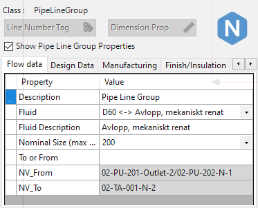
Update Line Group
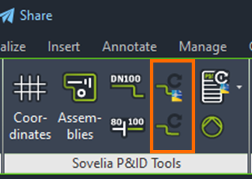
Sovelia P&ID Tools has two commands specifically for updating line groups with information about which nozzles a line is connected to. The command can be executed for either the active drawing of the entire project.
P&ID Lists
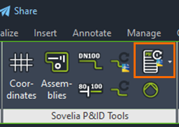
The P&ID Lists command is used to create lists in P&ID. The command uses Annotation blocks and sorts them into lists.
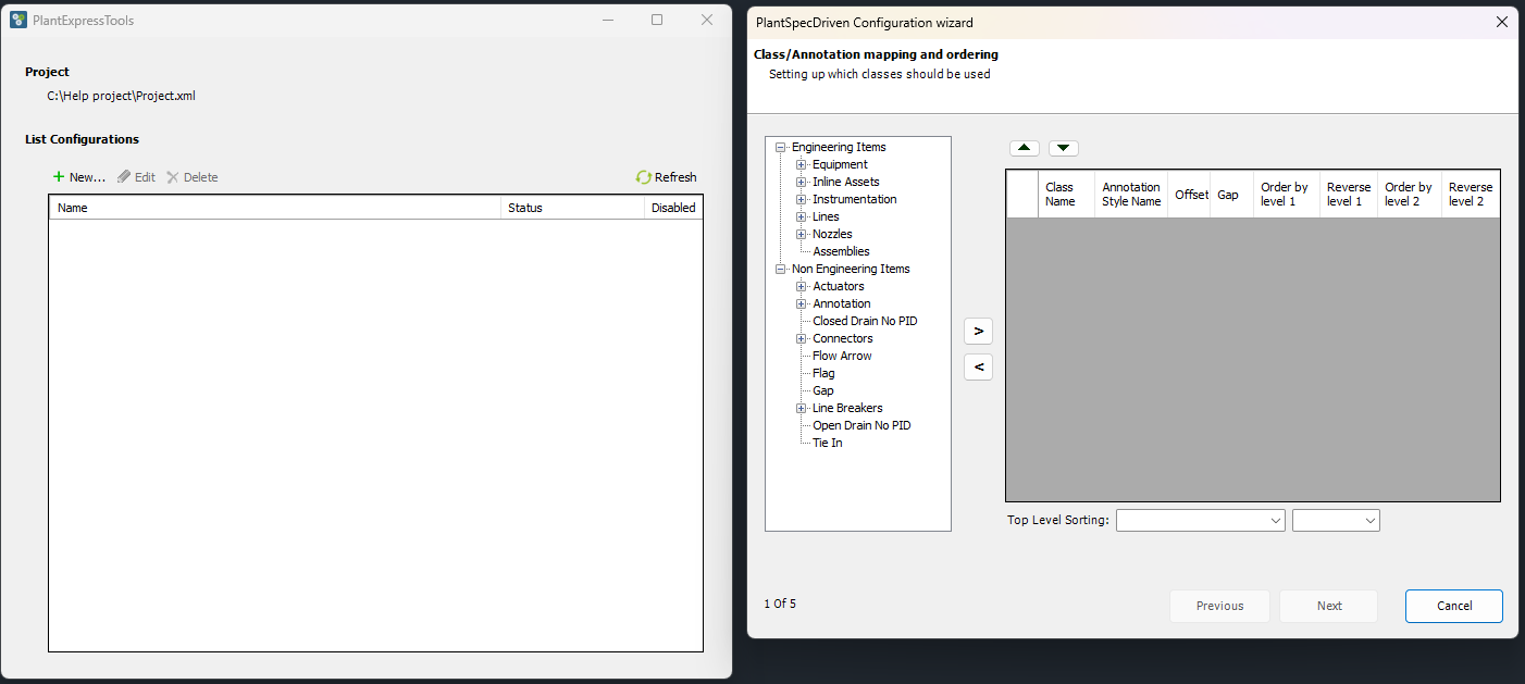
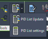
Clicking the down arrow on the command shows two options. The PID List settings is used to set up lists, and the PID List Update to make sure said lists are up to date.
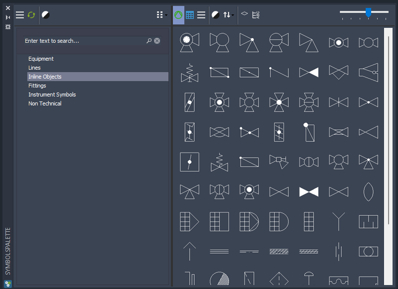
Symbols Palette
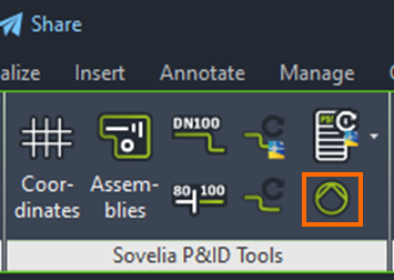
Sometimes while working the need might arise for a symbol which is missing from the tool palette. The Symbols Palette command searches the entire database, looking for a suitable P&ID symbol. Simply enter a text search or browse the categories. To place a symbol, simply press it and choose an insert point in the Plant 3D workspace.