
Description
Insert Sketched Symbols on parts in a view
Use Insert Sketched Symbols to place a sketched symbol on each part found in a view. The parts are found by selecting geometry from the parts in the view.
Start from Annotate ribbon on the Sovelia panel: 
| Command | Value |
|---|---|
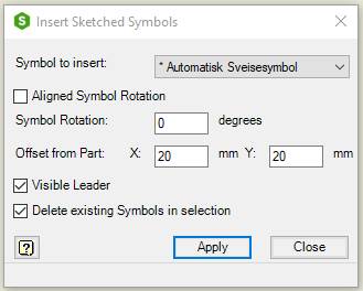
| Symbol to insert | Select a sketched symbol from the list: The list contains all the sketched symbols in the drawing. If there is a setup for Automatic symbols in Cadit Insert Sketched Symbols.ini, Insert Sketched Symbols will automatically insert a symbol according to criteria in the configuration file |
| Aligned Symbol Rotation | Rotate the sketched symbol to align with the selected geometry. Symbol Rotation option and Offset from Part X and Y option is turned off |
| Offset from Part X | Sketched symbol insertion point offset distance from selected part geometry in x direction |
| Offset from Part Y | Sketched symbol insertion point offset distance from selected part geometry in y direction |
| Offset from Part | Sketched symbol insertion point offset distance from selected part geometry, when aligned symbol rotation is used |
| Visible Leader | Show the leader from the part geometry to the sketched symbol |
| Delete existing Symbols in selection | Deletes sketched symbols same as the symbol to insert if they are selected in the view. |
| Apply | Inserts one sketched symbol to each part selected in the view. Only one symbol is inserted per part, even if more than one geometrical element from a part is selected |
| Close | Closes the dialog box |
See also Cadit Insert Sketched Symbols.ini