

Draw all plates used in an assembly
Makes a drawing of a plate in a model file or of all plates from current assembly. Plates are sheet metal parts or parts with a ct_cut_info code for plates. The program starts a new drawing file based on the Draw Plates template. Views of each plate in active assembly are placed into the drawing in sorted order. Plate thickness and material is the sort criteria.
There are three possible layout configurations:
The default is one sheet for each different material type and thickness.
It is also possible to get one sheet per plate or all plates on one sheet.
Each view is labeled with a configurable set of properties and other information, such as Item No and Quantity from Parts Only BOM in the current assembly, the assembly name, External dimensions, Material, File Name, Part Number, Description and some other properties. The views are scaled 1:1.
The default template file is Draw Plates.idw.
Edit the template file to customize the drawing options.
The template file can be changed in the configuration file.
If the template file type is idw, idw files are created, if it is dwg, Inventor dwg files are created.
Edit the Cadit Draw Plates.ini to change the configuration settings.
Start from 3D Model ribbon in a model file or Assembly ribbon or Tools ribbon in a assembly file, from the Sovelia panel: 
| Command | Value |
|---|---|
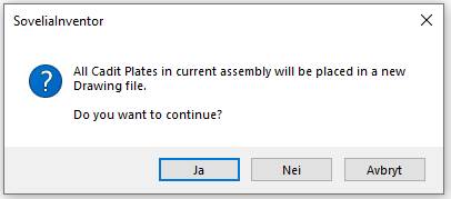
| Yes | Starts a new drawing based on the Draw Plates template and place a view of each plate in the active assembly into it in sorted order |
| No | Closes the dialog and exit the program |
| Cancel | Closes the dialog and exit the program |