

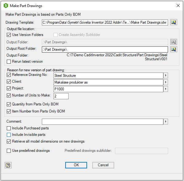
Manage Drawings for all parts in an assembly
Make drawings of all normal and phantom parts from current assembly. Purchased parts are optional. By use of version folders changes to the models are controlled and can be tracked. Drawings are made from a selected template or optionally copied from a predefined drawing.
A set of properties is added to the drawing files to control version information, assembly information and component information.
Start from Assembly ribbon or Tools ribbon, on the Sovelia panel:

| Command | Value |
|---|---|
| Drawing Template | Name of template for drawing creation. Default value is the previous value in the current assembly if the command has been used on the current assembly before. If not, it is the previous Template used by the command. If the field is empty the sample template file, Make Part Drawings.idw from the Template subfolder of the Local Configuration folder, will be used. If the template file type is idw, idw files are created, if it is dwg, Inventor dwg files are created. The template file type must not be changed after files have been saved in the output folder. Only files with the same file type will be considered for version changes |
 |
Browse for an idw or dwg template. |
| Output file location | Drawings can be made with use of version folders or in a single output folder. Version is not the same as revision, it means version of the assembly when the part drawings are made with Make Part Drawings. Without use of version folders all drawings are created in the Output Folder. With version folders the drawings are created in subfolders to the Output Root Folder. The first level is a folder with the same name as the current assembly. Under the assembly folder is the version folder. The first version is called V001, the next version is V002. A new version folder is made if there are changes to the parts or new parts are added or removed from the assembly. If a part has changed, the part drawing is moved from the previous version folder to the current version folder. Drawings of new parts added to the assembly are made in the current version folder. Drawings of parts removed from the assembly are moved to the current version folder and –DELETED are added to the file name. All parts in the assembly are documented under the assembly folder. The first version folder contains files unchanged since the first run. The next version folders have the files changed in the assembly at the present time. To have a complete set of drawings we need all files from all version folders. To have the last changes we need the files from the last version folder |
| --- | Use Version folder, Use version folder for the drawing files |
| --- | Create Assembly Subfolder, Creates a subfolder named as the assembly for the drawing files |
| --- | Output Folder, Folder to place the drawing files without use of version folders. A dot and a backslash first in the folder name give the current project folder. Default value is the previous folder name from current assembly or previous from the program. If empty a subfolder to the current project folder called Part Drawings will be used (.\Part Drawings) |
| --- | Browse for Output Folder. If a subfolder to the current project folder is selected the project folder name is replaced with a dot |
| --- | Output Root Folder, Folder to place the assembly and version subfolders. A dot and a backslash first in the folder name give the current project folder. Default value is the previous folder name from current assembly or previous from the program. If empty a subfolder to the current project folder called Part Drawings will be used (.\Part Drawings) |
| --- | Browse for Output Root Folder, If a subfolder to the current project folder is selected the project folder name is replaced with a dot |
| --- | Output Folder (Next Version Folder), Shows the name of the next version folder to be made. The folder is made if there are changes that make it necessary |
| --- | Rerun Latest Version, Run the program without numbering up the version number |
| Reason for new version of part drawing | If there are changes in the physical properties of the part, there will be made a new version of the part drawing. Other changes can optionally cause that too |
| --- | Reference Drawing No, Reference Drawing number. Check to make new drawings if changed. Use right click menu to cut, copy, paste, delete or insert recent values. Stored in the property ct_mpd_reference in drawing and assembly. |
| --- | Client, Client Name. Check to make new drawings if changed. Use right click menu to cut, copy, paste, delete or insert recent values. Stored in the property ct_mpd_client in drawing and assembly. |
| --- | Project, Project name. Check to make new drawings if changed.Use right click menu to cut, copy, paste, delete or insert recent values. Stored in the property ct_mpd_project in drawing and assembly |
| --- | Number of Units to make, Number of units to be produced of current assembly. Check to make new drawings if changed. Use right click menu to cut, copy, paste, delete or insert recent values. Stored in the property ct_mpd_units_to_make in drawing and assembly |
| --- | Quantity in Assembly, Quantity of part in current assembly. Check to make new drawings if changed. Stored in the property ct_mpd_qty in drawing |
| --- | Item Number in Assembly, Item number of part in current assembly Check to make new drawings if changed. Stored in the property ct_mpd_iam_item in drawing |
| Comment | Type in a comment for the version of the part drawings. Use right click menu to cut, copy, paste, delete or insert recent values. Stored in the property ct_mpd_idw_comment in drawing |
| Include Purchased parts | Check to make part drawings of parts with BOM structure Purchased |
| Include Invisible parts | Check to make part drawings of invisible parts |
| Retrieve all model dimensions on new drawings | Check to get all model dimensions on new drawings. The dimensions will be inserted arranged. |
| Use predefined drawings | Check to use predefined drawings. Drawings with same name as the part will be used instead of the template. The drawing must be placed in the same folder as the part or a predefined subfolder to this |
| Predefined drawings subfolder | Name of subfolder for predefined drawings. The folder is a subfolder to the folder of the part. If empty, the predefined drawing must be placed in the same folder as the part |
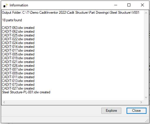
| OK | Runs the program. Shows the Information dialog, with information about parts, new parts, changed and deleted parts |
| --- | Explore, Closes the Information dialog. Opens the windows explorer in the output folder. The button is only available if Make Part Drawings has made changes or new drawings |
| --- | Close, Closes the Information dialog |
| Cancel | Closes the dialog box |
After the drawings have been made the Information dialog shows a report of the number of part drawing that have been made, changed or deleted.
| Command | Value |
|---|---|
| Explore | Opens the output folder in Windows Explorer. Select the files and open them in Inventor to finish the drawings |
| Close | Close the Information dialog |
The Make part drawings.ini file contains settings used by Make part drawings.
New part drawings are made according to certain rules which control number of views, scale, rotation, margins and gap between views. This is different for different component types.
The configuration file Cadit Make Part Drawings.ini contains values for the scale list, margins, gap, rotation and other settings.
The layout is according to this list:
| Component type | Criteria | Scale | Figure (click to Expand) |
|---|---|---|---|
| Sheet Metal Part, Flat Plate | Flat Sheet Metal parts. Property ct_cut_info has one of the following values: FPE1, FPEZ. | Scaled to fit all views in the border. Drawing base view from the flat pattern of the part. | 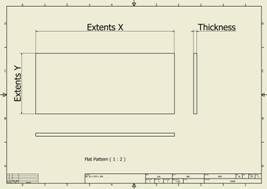 |
| Sheet Metal Part, Folded Plate or Folded Profile | All other Sheet Metal parts | Scaled to fit all views in the border. Drawing is divided in to, one half for the Flat Pattern and the other half for tree views of the folded model. | 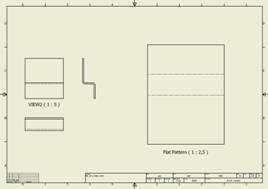 |
| Standard Part, Plate | Plates. Property ct_cut_info has one of the following values: PL, DPL, XY, XZ, YX, YZ, ZX, ZY, TXY, TXZ, TYX, TYZ, TZX, TZY, PXY, PXZ, PYX, PYZ, PZX, PZY. | Scaled to fit all views in the border. Base view orientation is aligned with the drawing border | 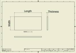 |
| Standard Part, Profile | Cut-length profiles, beams, yard goods. Property ct_cut_info has one of the following values: X, Y, Z, L, FPEL, RB. Frame generator or content center beams with property G_L or pipes with property PL | Scaled according to width of section view. User can manually break view to adjust the length | 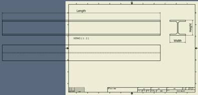 |
| Standard Part | All other parts | Scaled to fit all views in the border. Standard view orientation | 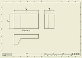 |
Make part drawing creates a set of properties on the part drawings. The values are set at the moment the program runs. They might be wrong if the part have been changed after the last run of Make part drawing.
| Property | Description | Value |
|---|---|---|
| ct_mpd_ipt_mass | Mass of the part. | Copied from physical property in part |
| ct_mpd_ipt_area | Surface area of the part. | Copied from physical property in part |
| ct_mpd_ipt_volume | Volume of the part. | Copied from physical property in part |
| ct_mpd_ipt_cogx | Center of gravity x-coordinate of the part. | Copied from physical property in part |
| ct_mpd_ipt_cogy | Center of gravity y-coordinate of the part. | Copied from physical property in part |
| ct_mpd_ipt_cogz | Center of gravity z-coordinate of the part. | Copied from physical property in part |
| ct_mpd_ipt_material | Material of the part. | Copied from material property in part |
| ct_mpd_iam_item | Item number of the part in the current assembly | Copied from parts only item number in assembly |
| ct_mpd_ipt_timestamp | Current part save time in Universal Time Code | Copied from save time in part |
| ct_mpd_qty | Quantity of the part in the current assembly | Total number counted in assembly |
| ct_mpd_units_to_make | Units to make of the current assembly | Units to make from property in assembly |
| ct_mpd_total_quantity | Total quantity to make of the part | Calculated from ct_mpd_qty and ct_mpd_units_to_make |
| ct_mpd_reference | Reference from the current assembly. | Copied from property in assembly |
| ct_mpd_client | Client from the current assembly. | Copied from property in assembly |
| ct_mpd_project | Project from the current assembly. | Copied from property in assembly |
| ct_mpd_version | Cadit Make Part Drawing run number that lead to new version of drawings. | Current version. Previous versions are numbered. |
| ct_mpd_idw_versiondate | Part drawing revision date. | Current version. Previous versions are numbered. |
| ct_mpd_idw_author | Part drawing author. | Current version. Previous versions are numbered. |
| ct_mpd_idw_comment | Comment from the current assembly. | Current version. Previous versions are numbered. |
| ct_deleted | Text to tag deleted part in drawing files. | Text from the configuration file Cadit Make Part Drawings.ini. |
| ct_scale | Main drawing scale.. | Value is based on scale of the first base view or the first Flat Pattern base view if it is a sheet metal part. |
See also Make Parts drawing.ini